
Accountants may have a fiduciary responsibility, but that really has nothing to do with PC board assembly. Change the “ry” to a “ls”, however, and you get fiducials, which does have something to do with PCB assembly.
A fiducial is essentially an alignment mark for surface mount assembly machines. High volume assembly requires them to ensure accurate registration and parts placement. Low volume assembly, like we do here at Screaming Circuits, doesn’t necessarily require them. (Some low volume shops do, so ask before assuming). Even if they aren’t required, they still help and are always a pretty decent idea.
 The basic idea is to create a non-reversal pattern with two or three fiducial marks on your board or panel. As you can see in the image above, the designer placed three fiducials around the board in a non-reversible pattern. Note that to protect the confidentiality of the board design, I obscured the circuit detail with this convenient robot head.
In terms of the specific construction of a fiducial, there are two things that are the most important: contrast, and accuracy of position.
Contrast comes from it being bare copper – make it 1 to 2 mm in diameter. Don’t cover it with solder mask. Make the mask opening 2 – 5 mm larger than the copper.
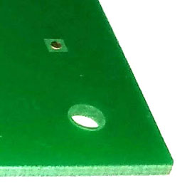
The image on the right shows closeup detail. This particular fiducial mark uses a square cutout in the silk screen. Most use a round cutout, but the shape isn’t all that important. The copper pad should be round, though.
Making it out of copper gives the positioning accuracy. I’ve been asked why silk screen markings aren’t acceptable. Silk screen isn’t always registered consistently, and is therefore won’t ensure accurate alignment. Don’t use silk screen as a fudicial or positioning mark of any kind.
Again, they’re generally required for high-volume manufacturing. We (Screaming Circuits) don’t require them for low-volume, but some assembly houses do. Even when not required, they’re still a good idea.
Duane Benson is the Chief Technology Champion at Screaming Circuits, a prototype PCB assembly electronic manufacturing company in Canby, Oregon.


