BJT, drivers, IGBT, MOSFET, MOV, optical isolation, optoisolator, relays,snubber diode, solid state relays, ssr, transorb, triac, tvs diode, varistor
Driver circuits
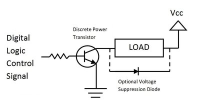
A typical digital logic output pin can only supply tens of MA of current. Even though they might require the same voltage levels, small external devices such as high-power LEDs, motors, speakers, light bulbs, buzzers, solenoids, and relays can require hundreds of MA. Larger devices might even need several amps. To control smaller devices that use DC, a transistor-based driver circuit can be used to boost the current to the levels needed for the device. When voltage and current levels are in the correct range, the transistor acts like a high-current switch controlled by the lower current digital logic signal. A discrete BJT is sometimes used instead of a newer MOSFET transistor especially on older or low voltage circuits as shown below. On mbed, any GPIO pin could be used for the logic control input to the circuit with DigitalOut.
Basic driver circuit using a BJT transistor
The transistor primarily provides current gain. PNP, NPN, or MOS transistors can also be used. The resistor used on the base of the transistor is typically around 1K ohm. On inductive loads (i.e., motors, relays, solenoids), a diode is often connected backwards across the load to suppress the voltage spikes (back EMF) generated when turning devices off. (Recall on an inductor V=L*di/dt, so a negative voltage spike is produced when turning the device off). Sometimes the diode is also connected across the transistor instead of the load (this protects the transistor). The 2N3904 shown below is a small discrete BJT transistor that can be used for a driver circuit needing less than 200MA. In this circuit with BJTs, Vcc can also be a higher voltage supply than the logic power supply. 6 or 12V DC is often needed for motors or relays. In battery operated devices, the load may be directly connected to the battery power and not pass through the voltage regulator. Many devices such as motors have a momentary large inrush current spike when they are first turned on and have a larger stall current, so be a bit conservative on the maximum current ratings.
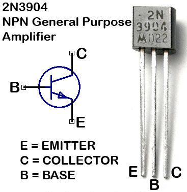 Depending on the current gain of the transistor used, some adjustments may be needed in the value of the base resistor. A high gain TO-92 transistor such as the ZTX689B can drive up to 2A at up to 12V in this circuit. A Darlington transistor pair contains two BJT transistors connected together for higher current gain. If a Darlington transistor in a TO-92 package such as a ZTX605 is used in the driver circuit, outputs of 1A at up to 100V are possible. At high current levels, the transistor might get a bit hot. Transistors can even get too hot and burn out, if the circuit is not designed correctly. The transistor has to dissipate the power (V*I) across its C-E junction (i.e., the switch point) as heat. This means that the transistor should either be completely “on” (saturation) or “off” (cutoff) to minimize heat dissipation and maximize efficiency. Larger power transistors have metal tabs on the case that can be connected to a heat sink for cooling. The pins on larger power transistors are often too large for standard breadboards and the spacing is not always compatible.
PWM Control
The logic signal (control) turns the transistor on and off to drive high current loads. For motor speed control or dimming lights, a digital PWM output signal is typically used for control instead of an analog output. Digital PWM is more energy efficient than analog as it significantly reduces the heat dissipated by the transistor (i.e., it is always completely “on” or “off”). For motors, the PWM clock rate is typically in the tens of KHz range. For lighting, it needs to be greater than 50Hz or perhaps 100Hz. Early studies for electric power systems showed that many people have headaches caused by lighting systems that use less than 50Hz AC even if they do not directly perceive a flicker. A Class-D amplifier uses PWM to drive audio speakers and the PWM clock rate is typically around ten times the highest frequency in the audio signal. A low pass filter is sometimes added on the output. The mbed PWMout Handbook page shows an example using PWM to dim an LED. Even when using PWM, some large transistors may require a heat sink for proper cooling. If the transistor gets too hot to touch, it needs a larger heatsink.
Driver ICs
As an alternative to using discrete transistors, special purpose driver ICs are also available that can drive multiple devices. These ICs contain several internal transistor driver circuits similar to the one just described above. A small number are still available in a DIP package that can plug into a breadboard such as the ULN2803 8-channel 500MA 50V driver seen below, but most new ones are surface mount ICs that will require a breakout board for use on a breadboard.

 The TI TLC5940 is a 16 channel driver IC with 12 bit duty cycle PWM control (0 – 4095), 6 bit current limit control (0 – 63), and a daisy chainable serial interface (SPI). Maximum drive current is 120 MA per output. It is handy for expanding the number of high current drive PWM outputs available. This IC was originally targeted for driving LED arrays. 16 PWM outputs might sound like a lot, but a humanoid robot might need over twenty to control all of the servo motors used the joints. In addition to the DIP package seen above, is it also available in surface mount. Sparkfun makes the breakout board seen below using the surface mount package. A TLC5940 code library is available for mbed. There is even a special version of an mbed code library just for servos that sets up a 16 servo array. Driver ICs may also require heat sinks or other cooling considerations when used at high current levels.
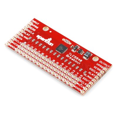 Devices that require several amps of current will need a more complex driver circuit with larger power transistors on heat sinks, and more than one transistor current amplification stage may be required. It is not advisable or reliable in the long term to connect several small BJT transistors in parallel to increase the current output provided by the driver circuit; a larger power transistor must be used. Driver circuits can be built using small discrete transistors such as the TO-92 size 2N3904 on a standard breadboard. If even higher current drive is needed, the larger power transistors used will not fit directly on a breadboard and the wires are not large enough. Having these devices already assembled on a small PCB will save prototyping time with mbed, so those options will be the primary focus here.
For speakers, an audio amplifier IC is often used to drive the speaker. New class D audio amplifiers actually use PWM.
MOSFETs
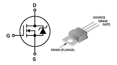
At higher voltage and high current levels, newer MOSFET transistors are more efficient than the older BJTs. In BJTs, the base current controls the switch, but in MOSFETs it is the gate voltage. A common N-channel RFP30N06LE MOSFET transistor symbol and pinout is shown below.
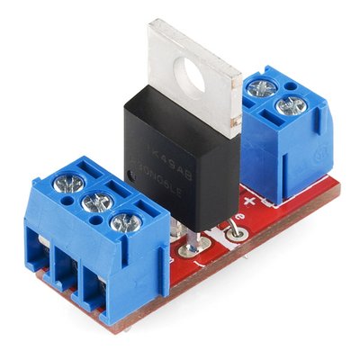
 The board seen above uses the RFP30N06LE MOSFET transistor rated at 60V and 30A for higher current loads. The trace size on the PCB and the wire size for the screw terminals limits loads to around 4A. The screw terminals are used for high current connections since the wires need to be larger than the standard breadboard jumper wires. The schematic is seen in the image below. This special MOSFET has a very low gate input voltage that works with 3.3V logic signals like those on mbed.
 A typical MOSFET runs just a bit more efficiently if the gate input is a bit higher than the supply voltage. Special MOSFET driver ICs such as the LTC1155 use a charge pump circuit to drive the gate voltage higher on higher voltage MOSFET driver circuits using a normal digital logic level control signal (i.e., useful when load voltage (RAW in schematic) is larger then the logic supply voltage). The LTC1155 is used with a MOSFET in many laptop PCs and cellphones to turn power on and off for power management and is available in an 8-pin DIP package or surface mount. Overvoltage and short circuit protection can also be added using the LTC1155. Some large MOSFETs including the one on the Sparkfun board already contain an internal snubber diode for driving inductive loads. If this is not the case, it would be a good idea to add an external diode when driving inductive loads.
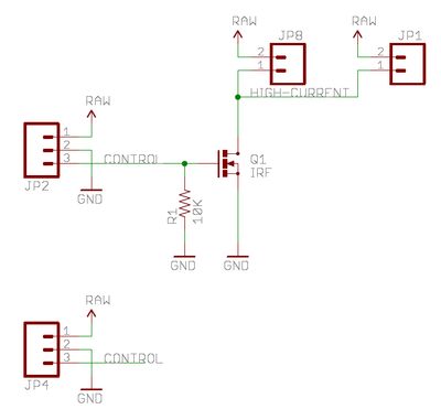 Any digital out pin can be used for control (connects to the control input of the driver circuit). If you plan on using PWM, select one of the mbed PWMOut pins. Keep in mind that mbed can only supply about 200MA of current for external devices via USB power, so an external DC power supply may also be needed for large loads. When using external DC power supplies for additional power (to RAW in schematic above), only connect the supply grounds together (i.e., and not mbed Vcc and RAW even if the voltage is the same).
IGBTs
The insulated gate bipolar transistor (IGBT) is a new type of semiconductor device used as an electronic switch in newer designs that combines high efficiency and fast switching. It is used in medium and high power applications such as appliances, electric cars, trains, variable speed refrigerators, air-conditioners, stereo systems that use switching amplifiers, and even welding machines. They can be connected in parallel to make devices with ratings up to 6000V and hundreds of amps. It has an isolated gate FET as the control input of a BJT.
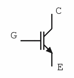
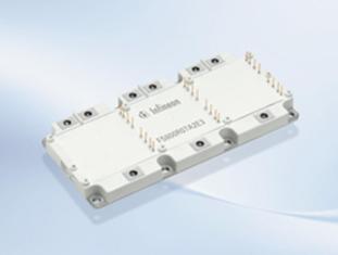 The IGBT module seen above is used to switch the drive motor in hybrid cars. It contains six IGBTs (3 Phase AC motor with variable frequency drive (VFD) using PWM) and is rated at 800A/650V. Many of the newer energy efficient home furnaces also have a variable frequency drive blower motor. A wide array of IGBT modules are available ranging from several amps to several thousand amps and in this range they can be more energy efficient than power MOSFETs.
Special Purpose Driver ICs
As an alternative to using several discrete power transistors mounted on a PCB, multiple driver circuits are often packaged in ICs targeted for particular applications to save space and reduce cost. Two of the most common examples are motor and LED driver ICs.
H-Bridge Driver ICs
To control and reverse a DC motor, an H-bridge circuit is used with two control signals and four driver transistors. This allows the current direction through the load to be reversed similar to swapping the wires on a DC motor.
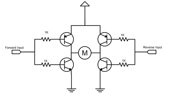 The basic H-Bridge circuit with four power transistors that provide drive current for the motor is seen above. In this circuit, you can think of the power transistors functioning as on/off switches. Two digital logic level inputs, forward and reverse, turn diagonal pairs of transistors on and off to reverse the current flow through the DC motor (M). In some very simple H bridge circuits, forward and reverse must not both be turned on at the same time or it will short the power supply. More advanced H-bridge circuits prevent this issue with a bit more decoding on the transistor inputs and add a dynamic brake feature. Dynamic braking can generate a bit more heat in the H bridge IC. MOSFETs are often used in newer H-bridge ICs instead of BJTs.
See http://mbed.org/cookbook/Motor for example code using an H-bridge driver to control the direction of a DC motor. It also uses digital PWM for motor speed control. Small H-bridge modules are available on breakout boards.
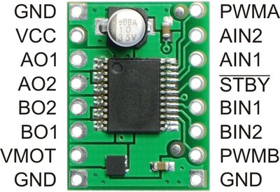 The small breakout board seen above uses Toshiba’s TB6612FNG dual H-bridge motor driver IC, which can independently control two bidirectional DC motors or one bipolar stepper motor. A recommended motor voltage of 4.5 – 13.5 V and peak current output of 3 A per channel (1 A continuous) make this a handy motor driver for low-power motors. Many small robots have two DC drive motors controlled by a dual H-bridge driver with PWM speed control. The Sparkfun magician robotcookbook page has code examples for mbed. Higher current H-bridge modules are also available.
The speed of DC motors varies with the load, and will also vary a bit from motor to motor even on identical motors. For accurate speed control under varying loads, feedback is typically required. Three cookbook projects, QEI, PID, and mbed Rover provide some additional background on how to use feedback for more accurate speed control of DC motors.
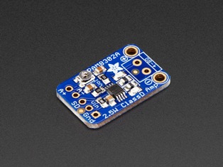 Many Class D audio amplifier ICs also use an H-bridge driver circuit. Examples can be found in the mbed component pages.
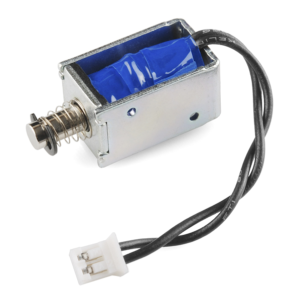 Some types of reversible solenoids also use a H-bridge driver, but a driver circuit for one direction is more common with a spring return.
Stepper motor driver ICs
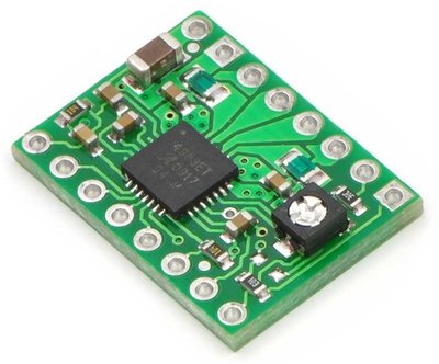
Stepper motors have multiple coil windings that need to be activated in the current sequence to rotate the motor shaft by a fixed angle without the need for position feedback hardware. Stepper motors are used in devices to provide low-cost accurate position control (i.e., moving the print head on an inkjet printer). Stepper motor driver ICs contain an H-bridge driver for each winding and often also include a small state machine or counter to sequence through the correct states to drive the motor. The typical control inputs are step and direction. The newest stepper motor driver ICs can respond to a variety of complex commands that even include the capability to move fractions of a step using PWM or perhaps move multiple steps automatically. The Pololu stepper motor driver breakout board seen below will drive a bipolar stepper motor up to 2A per coil using the Allegro A4988 DMOS Microstepping Driver IC. An example library to control stepper motors is available in the cookbook. A wide variety of stepper motor driver ICs is available.
 Brushless DC motors
Brushless DC motors are smaller and weigh less than equivalent DC (Brushed) motors, but they require a more complex speed control circuit. Brushless DC motors are used in most drones and they typically have 3 wires instead of 2. The electronic speed control (ESC) circuit needs a microprocessor with PWM outputs and three power MOSFET half-bridge drivers (two transistors each) to drive the three motor windings. Firmware can sense the motor’s back EMF and eliminate the need for an encoder to generate the correct sequence and timing of the PWM output signals which generate a three phase AC-like signal for the motor. Some high-end brushless DC motors also have encoders. The control signal in most ESCs for drones works the same as standard RC servo signals, a 1-2ms. wide pulse every 20ms. An mbed code example is available for an RC ESC using a Brushless DC motor for a racing drone.
 LED Driver ICs
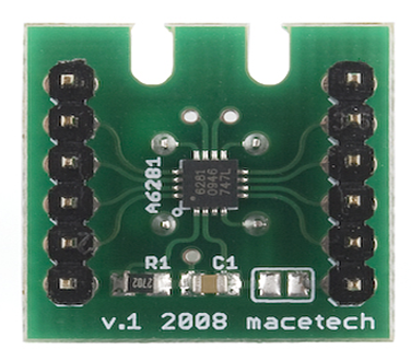
High-power bright LEDs require more current than the typical digital logic output pin can provide and they need a driver circuit. The small module seen below contains the Allegro A6281 IC with three 150MA driver circuits for a high-power red, green and blue(RGB) LED. It also includes PWM dimming hardware for each of the three driver circuits and it can generate 230 different colors and brightness levels. Code examples for mbed can be found on the Shiftbrite cookbook page. The modules can be chained together to build large LED arrays. With the rapid growth of LED lighting, quite a few LED driver ICsare available.
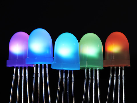
NeoPixel RGB LEDs contain three PWM driver circuits in a WS2811 driver IC in the same package as the RGB LED. They are available in many form factors (i.e., discrete, surface mount, panels, strips, rings, and breakout boards) and can be connected in long chains. Several Mbed code examples are available.
 Relays
Relays can also be used to switch high current and/or high voltage AC and DC devices using logic signals for control.
Electromechanical Relay
 An electromechanical relay contains an electromagnetic coil (right side of image above) that moves a metal arm to make and break an electrical connection. Electromechanical relays can be used to switch high current and also AC devices. They provide electrical isolation between the control signal and the load and are relatively low cost. No common ground connection between the control signal and load is needed. A standard digital logic GPIO output pin does not supply enough current to drive a relay coil directly. When using logic signals to control a relay, a driver circuit must be used to boost the current needed to energize the relay’s electromagnetic coil. The load is switched on and off using the relay’s metal contacts that move when the coil is energized. Since the metal contacts actually touch, relays will have less of a voltage drop across the switch point than transistor circuits. They are sometimes used to switch regulated power supplies on and off. Relays tend to more resistant to failure caused by high voltage surges than semiconductor devices.
Electromechanical relays do have some limitations for designers to consider:
- The number of lifetime ON/OFF cycles is limited by mechanical wear (typically 106 to 107 cycles)
- They have slow ON/OFF times – around 20 per minute. Too slow for motor speed control or dimming lights.
- Relay contacts can wear out due to arcing on inductive loads (perhaps as few as 105 cycles) even on rated loads.
- Oxidation on relay contacts can be a problem on low voltage analog signals. (around 2 volts is needed to initially punch through the oxidation layer that occurs between any two metal contacts)
- Worn out relays will sometimes stick due to mechanical wear and an audible click is typically heard during switching.
If a relay is being used to switch high current AC loads, the relay’s contact life can be greatly extended by turning it off near an AC zero crossing. This requires a zero crossing detection circuit for synchronization to the AC supply or a driver circuit that always turns off near zero such as a triac or SSR.
Many relays and solenoids are rated only for “intermittent duty”. This means that they should only be turned “on” for short periods of time and “off” for the vast majority of the time. If left “on” for long periods of time, the coil wire will overheat and it can melt through the thin insulation on the tiny coil wires and destroy the device. In an application that needs to leave a relay or solenoid turned “on” for long or undetermined periods of time a device is needed that is rated for “continuous duty”.
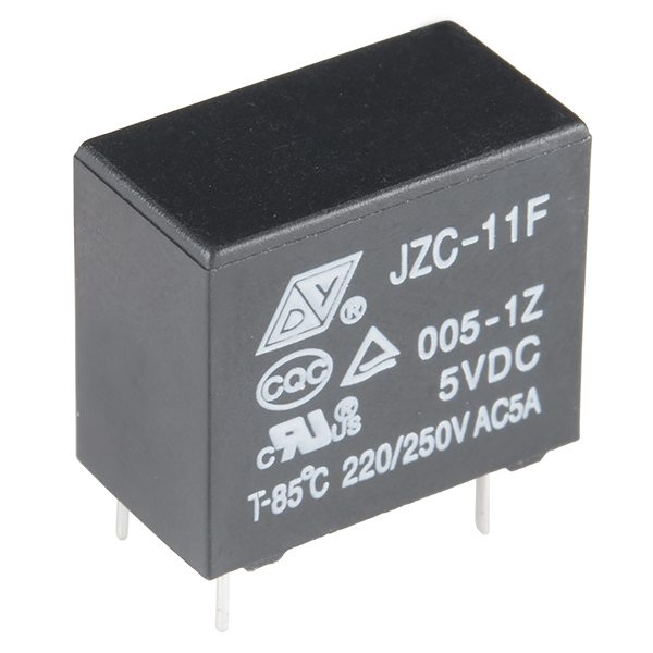 Most relays will not fit directly on a breadboard, but there are a few small ones (.5A to 5A) that will fit on a breadboard such as the one seen above. Breadboard jumper wires cannot handle very large current levels in any case. Even these small relays will still require a driver circuit and diode, so a relay breakout board might be just as easy to use.
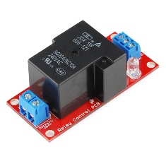 Sparkfun makes a low-cost relay board shown above that contains both the relay and the required driver circuit built using a discrete transistor. The relay coils on this relay require around 200MA at 5VDC. It is easier to drive relays like this that use a lower coil voltage. The relay board’s driver circuit is built using a BJT as seen in the schematic below. The relay can switch up to 220VAC at 20A using a logic signal for control, but the small PCB layout and screw terminals likely limit it to lower voltage and current levels to at least half of these ratings. A similar board is available from Sparky’s Widgets. It is probably wise to be very conservative on the maximum voltage and current ratings quoted for relays in datasheets.
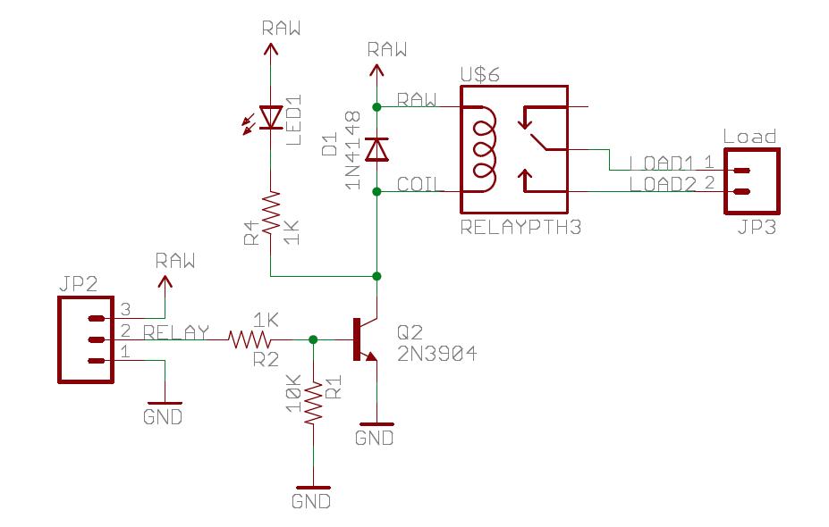 The snubber diode backwards across the relay coil absorbs the reverse voltage inductive spike that occurs when turning off the coil (i.e., V=Ldi/dt).
Any digital out pin can be used to control the relay (connects to the input of the relay driver circuit).
A demo using mbed with this code example for the Sparky’s Widget relay breakout board is available at http://mbed.org/users/4180_1/notebook/relay-breakout-boards/.
For safety and especially if you do not have prior experience working with high voltage AC, one of the sealed devices such as the Power Switch Tail II seen below would be a safer alternative to switch small household AC devices. It has an internal switch module and the high voltage connections are all enclosed in the case. Standard AC plugs are already attached and international versions of the Power Switch Tail are also available. The US version is also available from Sparkfun. A code example for mbed is available at http://mbed.org/users/4180_1/notebook/powerswitch-tail-ii/
In the schematic above, A1 is a VO2223 0.9A 600V optically isolated TRIAC (Phototriac) in a DIP package that is used to drive the mechanical relay. Note that it also has two MOVs included for surge suppression. It addition to the standard relay version, a Power Switch Tail with a solid state relay (SSR) is also available. SSRs and TRIACs will be explained in a later section.
The small Phidgets dual relay board seen below works in a similar manner to the Sparkfun board, but it has two relays.
Relays need to be selected based on both the input and output current and voltage rating. Since contacts can wear out on the output side be conservative on current ratings.
Reed Relays
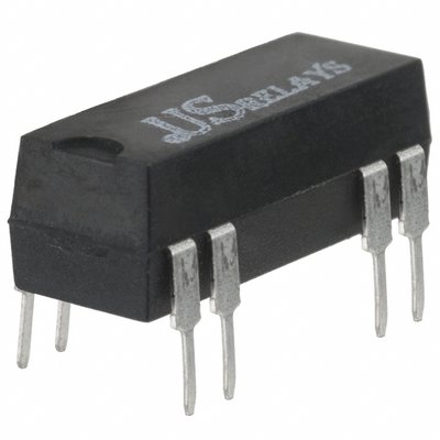 A reed relay is a type of relay that uses an electromagnet to control one or more reed switches. The contacts are of magnetic material and the electromagnet acts directly on them without requiring an armature to move them. Sealed in a long, narrow glass tube, the contacts are protected from corrosion, and are usually plated with silver. As the moving parts are small and lightweight, reed relays can switch much faster than relays with armatures. They typically switch lower current values than a large relay. They are mechanically simple, making for a bit more reliability and longer life. The coil current needed is lower (perhaps 10MA @5V) and in some cases a driver circuit may not be needed if the digital logic output has high drive current. Some reed relays already contain a snubber diode. If not, an external back EMF snubber diode would still be a good idea. Many are small enough to come in a DIP package that can plug into a breadboard.
Solid State Relays
In many applications, solid state relays can be used instead of electromechanical relays. Solid State Relays (SSRs) offer several advantages over electromechanical relays:
- Most have optical isolation between input and output load
- No moving parts – built using semiconductors
- Some are fast enough for motor speed control and dimming lights
- Resistant to shock and vibration
- Around 100X more reliable than mechanical relays
- Silent operation
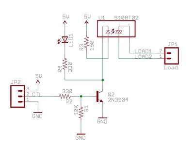
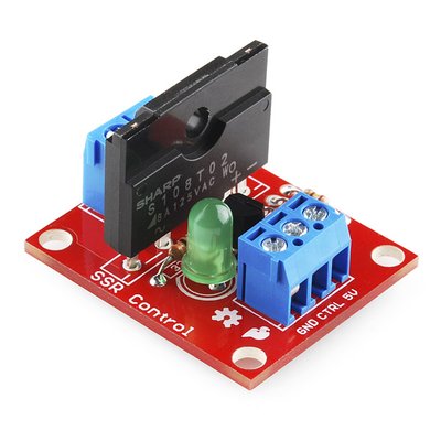 The schematic is shown below for the Sparkfun Solid State Relay board seen above. It uses a Sharp SSR module and can switch 125VAC at 8A (AC only – not DC). Note that it also requires a driver circuit and the external wire connections are the same as the relay board. A demo for mbed is available at http://mbed.org/users/4180_1/notebook/ssr-breakout-boards/
 Optical Isolation
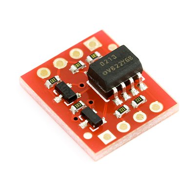
Optical or mechanical isolation (relays) between higher voltage supplies and computers is always a good idea. Not having to connect grounds between supplies helps in noisy industrial environments. Long wires can also pick up large transient voltages. One of the first projects to control and instrument an airport ended abruptly when a lightning bolt from a thunderstorm hit near the end of the runway and the ground wires carried the ground voltage transient spike all the way back to the control tower and blew up the computer. Most SSRs have an opto-isolator on the input. As seen below, Sparkfun also makes a small opto-isolator breakout board with small driver transistors on the output to isolate the computer output signals and convert them to higher voltage signals. It has limited current drive, but it could be added to the input side of a driver circuit to provide optical isolation. Opto-isolators are sometimes also used on sensor inputs to a computer. In this case, the sensor drives the input side and the output side connects to the computer.
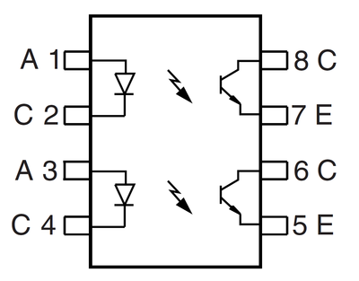
 As seen below, the ILD2213T optocoupler IC used on the Sparkfun board contains two optically coupled pairs consisting of a Gallium Arsenide infrared LED and a silicon NPN phototransistor. Signal information, including a DC level, can be transmitted by the LED via IR (infrared light) to the phototransistor while maintaining 4000V of electrical isolation between the input and output. Before reaching 4000V, other parts such as wires and connectors will likely short out first. Opto-isolators tend to be a bit slow to switch when compared to the speed of digital logic circuits. This device is in the five microsecond range. A few SSRs use reed relays on the input signal or feed the input through a DC to AC converter with a transformer for electrical isolation.
 Other SSR modules
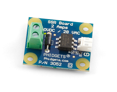
Unfortunately, solid state relay modules typically cost a bit more than mechanical relays. Many SSRs include a zero crossing circuit that turns on or off the device only when the AC voltage level is zero(a zero crossing). This also helps to reduce RF noise emissions generated by switching high current loads. The Phidgets SSR board seen below can switch both AC and DC voltages. It uses a small NEC/CEL SSR IC.
 Switching AC
Some solid state relays can also drive AC loads. This is possible using a TRIAC as in the Sparkfun Solid State relay board schematic above with the Sharp SSR module. The TRIAC symbol looks like two diodes connected in opposite directions as seen below. The gate control input (G) only requires a few milliamps and the AC load connects to A1 and A2. In the Sharp SSR module, the IR light from the LED drives the TRIAC gate input (provides optical isolation). A TRIAC’s gate input can be carefully time controlled in phase with the AC signal to dim lights, control motor speed, or adjust the power output to the load. Household light dimmer switches often use TRIACs.
 Two MOSFETs with their source pins connected together as in the Phidgets SSR module with the NEC/CEL SSR IC will also drive AC loads as seen below. The gate input is optically isolated and the MOSFETs drain pins connect to the AC load. This works since all MOSFETs have a substrate diode that always conducts current in the reverse direction (only the normal current direction can be switched). Be sure to check the SSR’s datasheet, SSRs can be AC only (TRIAC) or AC/DC(have two MOSFETs) or DC only(one MOSFET).
 SSR using two MOSFETs to switch AC loads with optical isolation
The power SSR tail module seen below can be used to dim incandescent or dimmable LED lights.
The PowerSSR Tail includes AC plugs and an SSR in an enclosed case
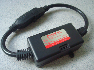 As seen in the schematic below, it contains a solid state relay built using an opto-isolator with digital logic inputs, a TRIAC for AC switching, and a MOV for surge suppression. A zero crossing and state detection tail module with isolation are also available. A code example for mbed is available at http://developer.mbed.org/users/4180_1/notebook/powerssr-tail-and-zerocross-tail/
Power SSR Tail Schematic
 The new PowerSSR and ZeroCross Tails are now available in one case and power cord, the PSSR ZC. It is the best choice now, if the dimmer function is needed.
Higher Power SSRs
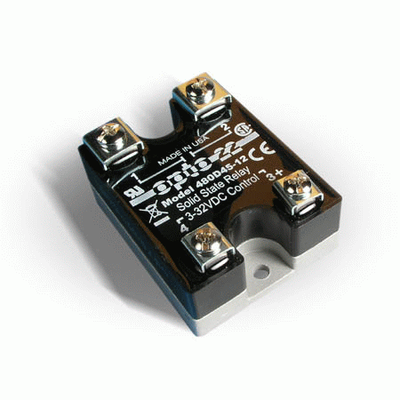
Opto 22 developed the first SSRs and makes a wide variety of DC and AC SSR modules including the large module below that will switch 480V AC at 45A with a 3V DC logic control input. They are frequently used in industrial automation systems. Heatsinks may also be needed on SSRs.
 Industrial Automation Systems & PACs
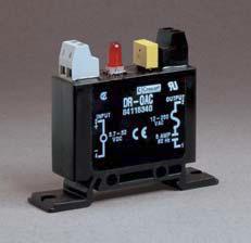
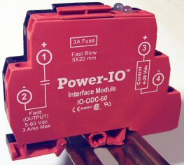
Programmable automation controllers (PACs) for industrial automation systems with a large number of inputs and outputs often mount a customized mixture of relays, AC/DC SSR modules, and AC/DC isolated input modules on special breakout boards or rail mount systems with screw terminals. Some SSRs mount directly to the rail. Several examples are shown below. They are handy whenever there are a large number of external I/Os to hookup with larger wires. A ribbon cable connector ties the digital I/O signals to the microcontroller. Such packaging works out well and helps to keep the wiring under control and organized.
A industrial automation relay room showing racks. Courtesy of Signalhead via Wikimedia Commons
 If a lot of external devices need to be connected in a prototype, many of these systems can be adapted for use with small microcontrollers such as mbed.
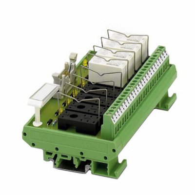 DIN rail mount optically isolated AC input module
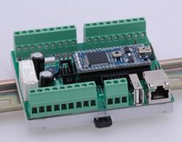
 Someone even has a DIN rail mount expansion board for mbed
Someone even has a DIN rail mount expansion board for mbed
 Home Automation Systems
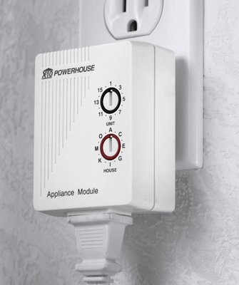
If you only need to control household AC devices, several low-cost home automation systems are available with small plug in modules for controlling household AC devices and dimming lights. X10 is of the first low-cost systems, and it uses signaling over the power lines to control each module. Switches on each X10 control module are configured by the user to select a unique address (0..255) for each AC device as seen below. X10 power line control signals are sensitive to distance and noise and will not cross over from one power phase to the other, just like home networking plug in devices. In addition to a power line interface to decode the control signals, a module contains a relay for appliances, or a triac to dim lights. A small interface device is available from X10 to send the control signals over the power line using a microprocessor. An easier to use RS232 serial interface for X10 can still be found, but it is no longer in production. There are two mbed X10 projects already available in the mbed cookbook, links to ways to interface to the X10 power line signals, and code for a wireless interface to the X10 wireless module. The X10 wireless receiver module then sends out the signals on the power line to control modules.
A plug in X10 appliance module can switch household AC devices
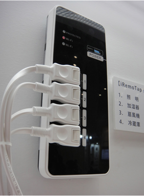
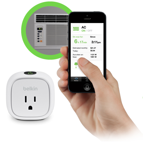
 Another home automation system is Z-wave. It uses RF signals to control the plug in AC modules. Insteon uses both power line and RF signals in a mesh network. One of the controllers from these systems could be interfaced with mbed to use these modules. WiFi controlled AC outlet strips are also starting to appear such as the one seen below. These systems work well in homes, but probably would not be appropriate for use in noisy safety critical industrial environments.
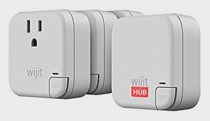
The Wijit is one of the newer low cost home automation examples. It has a Wi Fi hub that communcates to 10A relay controlled AC plug modules using low cost 434Mhz RF receiver and transmitter modules similar to those used car key fobs. Information on the WiJit is a bit hard to find, but some details and internal photos from the FCC approval are at https://fccid.io/O6PWJTHUB. They can be controlled from a free smart phone app.


