By Paul Pickering, Mouser Electronics
Over the last few years, the wireless charging market has seen a consolidation of standards and the introduction of new suppliers and new products. Meanwhile, some exciting technology developments are on the horizon. Here’s a look at where it’s been and where it’s going.
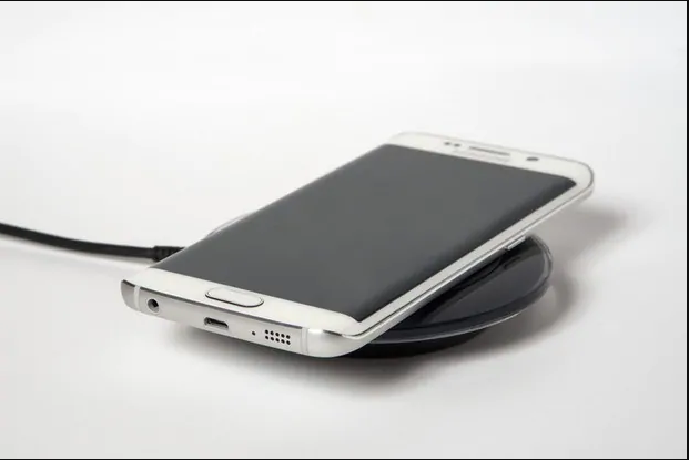
Wireless charging, also called wireless power transfer (WPT), is all the rage in trendy consumer wearables such as smartphones, smart watches, and fitness bands, but the idea itself has been around for more than a century: famed inventor Nikola Tesla demonstrated WPT between two lightbulbs in 1891! Wireless charging is attractive to industrial and automotive customers, too. With no direct connection, there is no chance of a stray spark causing an explosion, and a wireless charging system can be sealed against the effects of industrial solvents, dust, or gasses.
Widespread consumer use began in the 1990s with small consumer appliances such as toothbrushes and shavers and has accelerated over the last decade with the introduction of standardized specifications for WPT and the rise of portable and wearable electronics.
A Tale Of Two Technologies
Wireless charging systems use the principle of near-field charging (NFC): a transmitting coil generates an oscillating magnetic field that transfers energy through induction to a nearby receiving coil. In the typical configuration, a stationary charging station or pad contains the transmitter circuitry and primary coil, and the device to be charged houses the receiver with its secondary coil.
A fraction of the magnetic flux generated by the transmitter (primary) coil penetrates the receiver (secondary) coil and transfers power: the two coils essentially combine to make a transformer. The transfer efficiency is a function of the coupling (k) between the coils and their quality factor (Q).
A bidirectional communication channel, superimposed on the power waveform, allows authentication of the receiver and manages the power transfer. Unwanted metal objects between the transmitter and receiver can absorb energy and reduce efficiency or even heat up and pose a safety hazard, so foreign object detection (FOD)is also incorporated into current systems.
WPT developers are working on two technologies: inductive charging uses two closely adjacent and tightly-coupled coils; resonant charging uses two coils tuned to a common resonant frequency. Although both techniques use inductive coupling, the term “inductive charging” usually refers to the “tightly-coupled” variety.
Inductive Charging Overview
Inductive charging is the choice for low-power portables and wearables and is the only variant in high volume production, so we’ll concentrate on that, and discuss resonant charging at the end.
This method is efficient but is highly sensitive to coil misalignment. Power transfer also falls off rapidly with distance due to the inverse square law relationship. For high efficiency, the distance between coils in consumer applications is typically less than 7mm; if the user moves the receiving device, the system detects the drop in efficiency and terminates power transfer.
Figure 2 shows the block diagram of an inductive wireless charging system using two Rohm devices; these are discussed below. In most applications, a wireless charging system also includes two other blocks: an AC/DC power supply to supply charging power to the transmitter and a Li-Ion battery charger after the receiver.
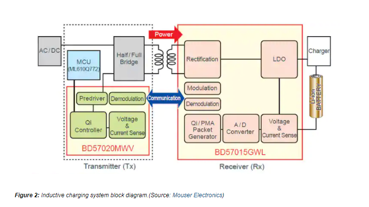 There are two competing inductive standards. The Wireless Power Consortium (WPC) controls the Qi (“Chee”) standard which has an operating frequency of 100– 200kHz; the AirFuel Alliance supports AirFuel Inductive, operating at 100– 350kHz. Both systems achieve an overall efficiency greater than 70%.
Many manufacturers support both standards. Samsung’s Galaxy S6 and S7 smartphones, for example, include both Qi and AirFuel charging.
In both Qi and AirFuel systems, the transmitter transfers wireless power to the receiver, but the receiver side controls the amount of power transferred. The receiver communicates with the transmitter by changing the load seen by the primary; the Qi standard specifies a 2kbps date rate with biphase bit encoding. The AirFuel standard defines six different communications symbols; each AirFuel receiver has a unique six-byte ID that it sends to the transmitter at startup.
A wireless system delivers much less power than its wired counterpart, so it takes longer to charge a battery, but manufacturers are addressing this by increasing power levels. WPC v1.2, introduced in 2015, can deliver up to 15W, compared to the 5W of earlier revisions.
Wireless Transmitter
During operation, the transmitter spends most of the time in a low-power “snooze” mode and wakes up at intervals to check whether a receiver is present. After detecting the presence of a secondary coil, the transmitter authenticates the receiver, then begins power transmission. If the authentication fails, it goes back to sleep. The secondary side maintains full control over the power transfer using predefined communication packets that handle functions such as identification, authentication, desired power level, and detection of errors.
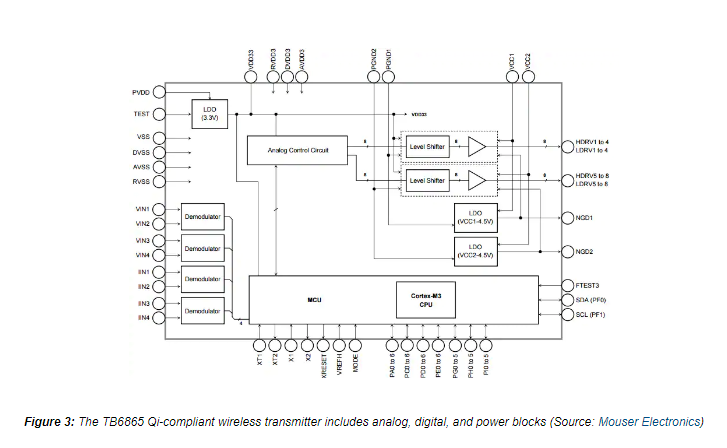 Toshiba’s TB6865AFG, shown in Figure 3, is an example of a Qi-compliant wireless transmitter. The TB6865AFG is a complex “system on a chip” (SoC) device that incorporates a 32-bit ARM Cortex-M3 processor core with 128 kilobytes flash memory, as well as the pre-drivers needed to implement a full-bridge inverter for driving the power coil. Other blocks include three low dropout (LDO) linear regulators and four demodulators to decode the commands from the receiver.
Wireless Receiver
Like transmitters, wireless receivers are also complex SoC devices. Rohm’s BD57015GWL, for example, integrates a fully synchronous rectifier circuit with low-impedance FETs, a packet controller that handles both Qi and AirFuel communication, and an open-drain output driver to communicate with the power transmitter via amplitude modulation. This device provides an adjustable, regulated voltage output and complies with both the Qi Medium Power standard and the AirFuel standard. Rohm also offers a matching transmitter, the BD57020MWV, that meets the Qi low- and medium-power specifications.
Transmitter and Receiver Coils
To ensure interoperability between devices from different manufacturers, the Qi standard contains detailed requirements for transmitter charging coils. The specifications define the coil electrical characteristics, geometries and materials. The specification for the A11 coil, for example, defines a single-layer circular coil with ten turns of wire mounted on a ferrite base. The coil has an input operating voltage of 5V, 6.3µH inductance, and a maximum DC resistance (DCR) of 60mΩ.
The A6 specification, with its three coils, reduces sensitivity to misalignment by increasing the available charging area; the tradeoff comes in a larger bill of materials (BOM) cost since each coil requires a separate driver.
Transmitter and receiver coils are typically made from special Litz wire; this contains many insulated strands wound into a special pattern that minimizes the skin effect and reduces proximity losses. Both coils should be similar in size for maximum energy coupling. For example, TDK wireless charging coils for Qi-capable mobile devices use a proprietary, flexible, thin metal magnetic sheet to achieve a thickness of only 0.52mm. The coils also have a small height and an output current of 0.5 to 0.6A.
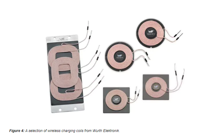 Figure 4 shows wireless charging coils in a variety of form factors. The A6 coil is on the left.
The receiver coil must be very thin to fit into a portable or wearable package but still robust enough to withstand high levels of vibration and shock. Since every smartphone, fitness band, and electronic device is different, receiver coils have tended to be custom designs. Texas Instruments offers a series of application notes on the coil design procedure.
In standard products, Vishay/Dale’s IWAS series is the first commercially-available receiver coil family that meets the Qi specification for 5 or 7V charging. The IWAS-3827EC-50 coil, for example, can handle up to 10W of power. It is a fifteen-turn design with 10.7µH inductance and 183mΩ DCR; mounted on a high-permeability shield, it measures approximately 38 x 26 x 1mm.
Transmitter and Receiver Modules
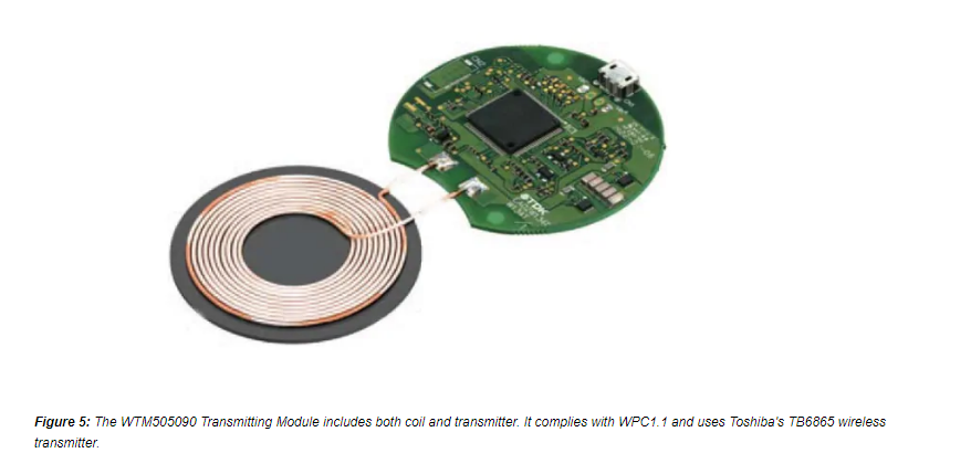
Several manufacturers offer modules that include both the coil and the transmitter or receiver. Figure 4 shows TDK’s WTM505090 transmitter module that consists of the transmitter PCB with the Toshiba TB6865AFG discussed earlier, plus the transmitter coil.
 WPT Development Tools
Several development kits and tools are available to help designers get started with wireless charging. IDT offers the WP3W-RK reference kit for applications up to 3W. The kit includes both the transmitter and receiver, together with three coil sizes to accommodate different power levels. A turnkey reference design, layout module, and BOM allow for quick development of prototype designs.
On The Horizon: Resonant Wireless Charging
Near-field inductive charging is the dominant technology today, but two other approaches are just over the horizon that offer wireless charging over a longer distance.
Resonant charging, the other near-field WPT technology, is less efficient than inductive charging but operates over a longer range and is more tolerant of coil misalignment. A resonant charging system doesn’t rely on the precise coil positioning required for the tightly-coupled system. Instead, the two coils are loosely coupled but tuned to a common resonant frequency. Advantages of this approach include the capability to charge multiple receivers simultaneously; also the two coils can be significantly different in size.
Resonant technology is an attractive option for many industrial and automotive applications. One reason is that they demand more positioning flexibility than available in an inductive charging system. Parking an electric vehicle over a floor-mounted charging station is hardly conducive to precise alignment, and it’s usually not feasible to position the transmitting and receiving coils a few millimeters apart.
An automobile requires higher charging power but luckily has more space available to mount the coils. The SAE, the standards-setting body for the automotive industry, is developing SAE J2954, a resonant charging standard for automobiles. J2954, scheduled for final release in 2018, defines three levels of charging for both light-duty and heavy-duty applications, WPT1 (residential: 3.7kW), WPT2 (private/public parking: 7.7kW) and WPT3 (fast charge: 11kW).
For consumer applications the WPC has also added a resonant option to Qi which has a range of up to 45mm, allowing chargers to be mounted under a desk or table. The AirFuel Alliance, too, has a resonant charging specification.
The development of commercial resonant chargers has lagged that of inductive chargers, and few commercial products are currently available.
Just Over The Horizon: Far-Field Charging
The Holy Grail of wireless charging, of course, would be to remove the distance restrictions entirely: your smartphone or tablet would trickle charge continuously no matter where you were – with “trickle billing” too, of course!
That’s the domain of far-field WPT, a technology that transfers power via radio waves (radiative coupling) rather than near-field magnetic induction.
Truly ubiquitous charging is not in view, but the first step is to provide power at distances from a few centimeters to a few meters to benefit multiple users in an enclosed space such as a coffee shop. Among the companies developing far-field RF solutions are Ossia, who showed an updated version of their Cota system at CES 2017. The system relies on a network of 256 antennas transmitting at 2.4GHz where the antennas transmit beamformed focused power to an authenticated receiver in response to an omnidirectional “low power” alert. The transmitter network detects the receiver location by analyzing the incoming multipath signal, then returns power back along the same paths. As the receiver moves, the transmitter revalidates its location every 10ms. The system can charge multiple receivers simultaneously with a maximum range of 30ft.
Another option being investigated is ultrasonic sound waves. Unlike electromagnetic (EM) energy, ultrasonic waves do not interfere with communication and do not cause EMI or harmful ionizing effects. In 2011 Santa Monica, California-based uBeam announced the development of a system operating at 45-75kHz, above the hearing range of humans, pets, and wildlife. An ultrasonic transmitter establishes a line-of-sight connection with a mobile receiver, perhaps embedded in a smartphone case, and passes power and data until the connection is lost. Although a successful proof-of-concept demonstration occurred in February 2017, commercial products are still several years from fruition.
Conclusion
The WPT ecosystem is a complex one with two well-supported competing standards, an increasing number of commercial products, and some radical new ideas in development. Mouser Electronics offers a wide range of products that support both versions of the market-leading inductive charging technology, in addition to a number of development tools.


