Testing in embedded systems is very important to ensure up-to marks performance of the embedded chip and end device both. Since embedded systems are much more complicated in nature & sophisticated in structure, hence the testing procedure became very complex. In addition modern embedded systems, operates on very sensitively on specification. Changes in microns can lead to failure of the entire device, thus requires to be tested very accurately. Such requirements lead of specifically designed test & measurement from global leaders. In this survey we have talked to some of the leaders in the testing industry providing solutions for embedded systems presented their views on solutions & challenges to test a given embedded system.
As interest in the Internet of Things and mobile devices continues to grow, companies are recognizing the value of embedded systems to collect data and control machinery. From software in cars and trucks to mobile medical devices and home appliances like refrigerators and even toothbrushes, embedded applications are permeating our world. With a great level of involvement of embedded systems in our day to day electronics to satellite systems, so increase the complexities of the embedded systems and the requirement of testing. Testing takes on greater importance with embedded applications. Testing embedded systems takes on an added importance that includes testing for adherence to requirements and systems integration testing.
“Test activities are important in any system, but in the embedded world, they can be a little more important because a lot of our embedded systems are life critical.”
Requirement of Testing Embedded Systems
Real-time and embedded systems are becoming increasingly sophisticated, with hardware designs continuously evolving. Next generation embedded systems are increasingly focusing on human interactive designs, high throughput architectures, innovative thermal management and multi-core technologies capable of executing complex algorithms on real time operating systems. The multi-touch technology, machine vision, and gesture, voice and motion recognition has made interfacing between a human and machine even more simplified and intuitive. The evolving wireless technologies have now formed an integral part of embedded systems and battery operated devices. The evolving concepts of Internet of Things (IOT), cloud computing and mechatronics will increase the penetration of embedded devices in every facet of the human life. The increasing complexity in embedded systems along with associate wireless & IoT modules, have makes testing a given embedded system very difficult and specialized job. Dedicated equipments are required and used for testing embedded systems, designed to test crucial specifications.
Tektronix India

Sai Venkat Kumar B, India Marcomm said, “With the complexity of modern embedded designs coupled with the growth of wireless, it has become increasingly costly to give designers all the tools they need for efficient debug and troubleshooting. Recent research shows over 25% of oscilloscope users now use a spectrum analyzer multiple times per week, and over 40% of embedded design projects include some form of wireless capability. One of the emerging trends in the global test and measurement equipment market is the miniaturization of equipment that remains flexible and easy to use. This has been pushing vendors towards incorporation of multiple measurement tools within an oscilloscope, in both bench-top and portable versions, which represents a growing and positive trend for oscilloscope users. The multiple measurement channels can be triggered in synchronization, without the need to fine-tune complex external clock arrangements. Today, testing of embedded equipments have moved to another level with the inclusion of wireless RF signals. Analog, digital and now RF signals are coming together to the embedded domain and creating significant changes on how work is done in designs houses and research centers specifically with respect to analyzing those signals in as short a time as possible. Engineers involved in mixed signal embedded designs need to work in three domains. Consequently Tektronix has evolved its mainstream oscilloscope line-up to ensure that customers will have access to analog, logic and RF capabilities. For instance, recently Tektronix has announced MDO-4000B Series of mixed domain oscilloscopes as an answer to the market requirements. First introduced in 2011, Tektronix delivered the world’s first mixed domain oscilloscope that could capture time-correlated analog, digital and RF signals for a complete system view of a user’s device, available analog bandwidth range from 100 MHz to 1 GHz with a 2.5 or 5 GS/s sample rate and a 20 Mpoints record length. In February 2014, it has launched the industry’s first six-in-one instrument with the Tektronix MDO-3000 Series of Mixed Domain Oscilloscopes, each of which includes a spectrum analyzer and an optional logic analyzer, protocol analyzer, arbitrary function generator, and digital voltmeter. This series offer 100 MHz to 1 GHz bandwidths along with a spectrum-analyzer channel matching the scope’s bandwidth. Optionally, the spectrum-analyzer channel on any model can be expanded to 3 GHz along with a 3 GHz capture bandwidth. Tektronix has added RF capability to its mainstream oscilloscopes to accelerate the adoption of mixed domain capability in the market and move it beyond a niche application. The proliferation of consumer electronics with capacitive touch screens and intuitive operation is creating a new set of user expectations that as a test and measurement vendor we are continuing to track and evaluate. The influence of the consumer world will change expectations on test equipment to start having smart-phone type interfaces, instrument control though tablets, and more customization with ‘widgets and apps’. We believe the market will continue to see more integration of test equipment on the design engineer’s lab bench into a single product, and Tektronix believes from its core that this product will fundamentally be a scope. There will be more miniaturization and improved performances in modular based scopes. Product range of Tektronics for testing embedded systems is:
- Oscilloscopes: a) Tektronix MDO3000 Series of Mixed Signal Oscilloscopes, b) Tektronix MDO4000B Series of Mixed Signal Oscilloscopes
- Embedded Serial Technologies:
- CAN / LIN / FlexRay: Tektronix offers built-in analysis for CAN, LIN and FlexRay serial buses in its bench and lab oscilloscopes. With this design engineers can automatically trigger, decode and search for serial packet content like start of frame, identifier, data and more, right on their oscilloscope.
- I²C / SPI: Tektronix offers built-in analysis for I2C and SPI serial buses in its bench and lab oscilloscopes.
- RS-232 / RS-422 / RS-485 / UART: Tektronix offers built-in analysis for RS-232, RS-422, RS-485 and UART serial buses across its bench and lab oscilloscopes.
National Instruments India

Satish Mohanram, Technical Marketing Manager, “The traditional way to test embedded systems has been to build hardware boards that represent a part of a big system(the system the embedded system is going to control – Plant) capable of generating signals that represent real I/Os as a part of bench testing.
First, creating all the needed hardware boards is costly.
Second, the performance requirements of sophisticated embedded systems are so demanding that it is no longer possible to build boards that allow adequate measurements to be taken.
Finally, and most importantly, this bench testing approach is based on a sequential design process where hardware is developed, plant model prototypes are built and software development begins.
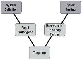
To overcome these limitations control design engineers have adopted a highly efficient design process often referred to as the “V” diagram. Though originally developed to encapsulate the design process of software applications, many different versions of this diagram can be found to describe different product design cycles. The one given below is typically what is used in Electronic Control Unit(ECU) design cycle which can be extended to building any embedded system.
 In this diagram the general progression of time in the development stages is shown from left to right. However, this is often an iterative process, and the actual development will not proceed linearly through these steps. Instead, one will spend time in each step and even have to backtrack from time to time. The goal is to make this cycle as efficient as possible by minimizing the amount of backtracking between steps as well as the time spent in each step.
The y-axis of this diagram can be thought of as the level at which the system components are considered. Early on in the development, the requirements of the overall system must be considered. As the system is divided into sub-systems and components, the process becomes very low-level down to the point of loading code onto individual processors.As one develops these embedded systems, it can be seen that test is an integrated strategy in every level at which the system that is being implemented. Afterwards, components are integrated and tested together until such time that the entire system can enter final production testing.

The software embedded in today’s complex systems defines its functionality. This poses an interesting challenge for many test engineers because most stand-alone instruments cannot change their functionality as fast as changes in the (Device under Test)DUT due to the fixed user interface and firmware that must be developed and embedded in the instrument. Thus, test engineers are turning to a software-defined approach to instrumentation, so they can quickly customize their equipment to meet specific application needs and integrate testing directly into the design process. For years, test engineers have taken advantage of software packages such as LabVIEW to customize measurement systems and reduce cost vis-a-vis traditional boxed instruments. Not only does this approach provides flexibility, it also gives test engineers the ability to take advantage of the performance provided by the latest PC, CPU, and bus technology.
Hardware In Loop (HIL) simulation is a powerful test methodology that gained popularity to test embedded control systems more efficiently. When testing embedded control systems, safety, availability, or cost considerations can make it impractical to perform all of the necessary testing using the complete system. People use HIL simulation to simulate (on an off the shelf measurement grade platform) the parts of the system that pose these challenges, and hence enable thorough testing of the embedded control device in a virtual environment before proceeding to real-world tests of the complete system. This new approach has gained prominence, as companies are able to improve reliability and achieve better time-to-market in a cost-effective manner despite the increasing complexity of systems.
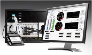
An HIL test system consists of three primary components: a real-time processor, I/O interfaces and an operator interface. The real-time processor is the core of the HIL test system. It provides deterministic execution of most of the HIL test system components such as hardware I/O communication, data logging, stimulus generation and mathematical model execution. A real-time system is typically necessary to provide an accurate simulation of the parts of the system that are not physically present as part of the test. The I/O interfaces consists of analog measurement and control signals, digital, fault simulators and bus signals that interact with the unit under test. One can use them to produce stimulus signals, acquire data for logging and analysis and provide the sensor/actuator interactions between the electronic control unit (ECU) being tested and the virtual environment being simulated by the model. The operator interface communicates with the real- time processor to provide test commands and visualization. Often, this component also provides configuration management, test automation, analysis and reporting tasks.
While off-the-shelf test and measurement hardware have traditionally been fixed in capability, National Instruments is leading the way in providing more open and flexible measurement devices based on field-programmable gate array (FPGA) technology. In short, FPGAs are high-density digital chips which the user can customize, giving test engineers the ability to directly incorporate their custom signal processing and control algorithms into measurement hardware.
National Instruments provides a wide variety of real-time processing options for implementing HIL test systems. Because they are all based on open industry standards, you can be assured that they always deliver the latest advances in PC technology to your HIL test system and always meet future test system requirements.PXI is an open, PC-based platform for test, measurement, and control. It offers a wide variety of real-time processor options including several high-performance dual- and quad-core processors. With more than 1,200 products from more than 70 vendors, PXI is the platform of choice for thousands of companies worldwide.
National Instruments also provides several options for implementing minimal-cost, small-footprint HIL test systems. NI CompactRIO is a low-cost reconfigurable control and acquisition system. The system combines small size with an open embedded architecture powered by reconfigurable I/O (RIO) field-programmable gate array (FPGA) technology.
This technology combines a real-time processor with a user-programmable FPGA that you can use to create custom I/O personalities as well as to off-load model execution and signal processing from the real-time processor for increased HIL test system performance.
Conclusion
Accurate results in testing embedded systems can be achieved thanks to professional test equipments we have in market that ultimately helps trouble-free designing of sophisticated electronics.


