 IGBTs are key components in power electronics and are mainly used where fast switching is essential, for example in inverters or motor control systems. Their drivers are powered through small, highly efficient DC/DC converters that play a crucial role for the reliability of the entire system. It is therefore very important that the correct converter model is chosen.
IGBTs have become indispensible in power electronics. Due to their capability to switch high powers with minimum current, they have become the preferred solution in many types of circuits, including modern frequency converters. In times of rising electricity costs, frequency converters are among the most effective solutions for the efficient operation of production plants. The primary task of frequency converters is regulating the speed of a three-phase asynchronous motor. As the frequency of the power grid determines the motor speed, changing the frequency enables operators to change the speed of the motor.

Design of standard frequency converter
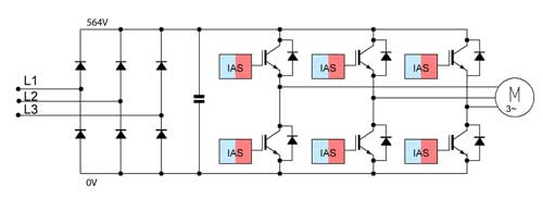
A frequency converter consists of three main components, namely the rectifier, the intermediate circuit and the inverter (see figure 1). In the power rectifier, the alternating current is converted by means of a three-phase bridge circuit into pulsed direct current. This current is smoothed in the intermediate circuit capacitor. Subsequently, the output voltage and frequency are adjusted in the inverter. The main components of the inverter are 6 IGBTs that are arranged in pairs on three branches. The IGBTs control the rectified intermediate circuit voltage output by means of pulse width modulation (PWM).
IGBT control
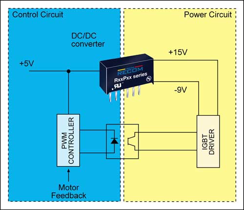
The IGBTs are powered and controlled by means of IGBT drivers integrated into the power circuit where they float in line with the input voltage. There is thus a need for electrical insulation. Optocouplers act as insulators for the control signal. For the supply power, the insulation is normally provided by two reinforced insulated DC/DC converters.
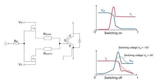
IGBTs thus combine the characteristics of MOSFETs at the input end and bipolar transistors at the output end. They can be controlled with minimum current. When through-connected, they show minimum voltage drop along the collector-emitter path. IGBTs are thus the ideal devices for the switching of high voltages and currents with minimum power consumption. During the switch-on process, it is important that the gate capacity is charged as quickly as possible. This, however, results in short-term current peaks. The gate resistance RG ensures that the longest permissible switching time at just about acceptable di/dt is achieved. During switching off, the voltage of the gate capacity must be reduced as quickly as possible. This is done by applying a suitable control voltage VG-. With symmetric power supply and +15V, which is required for IGBTs to switch on reliably, the control voltage should thus be -15V. If the gate charge drops too quickly, the components of the device would, however, be exposed to huge voltage peaks. In order to protect the components against such peaks, the control voltage is normally reduced during switching off. Tests have shown that -9V is a good compromise, as the gate is discharged sufficiently quickly at acceptable dv/dt values. Figure 2 shows the respective current and voltage curves. Developers of IGBTs have thus to make a choice: they can opt for a compact design with a single converter and symmetric ±15V, or choose a more costly, and less compact, solution with supply through two separate converters with +15V and -9V.

The latest products on the market are IGBT converters. These devices are perfectly adapted for combination with IGBT drivers, and feature dual asymmetric outputs of +15V and -9V for the supply of the drivers (see figure 3). As a single converter is thus sufficient, they cater for compact solutions and can help save money.

Why insulation is crucial for a long service life
At first sight, given an intermediate circuit voltage of around 560V, insulation strength does not appear to be a huge problem. As a rule of thumb, one would expect that insulation by twice the intermediate circuit voltage should be more than sufficient. When taking into account the high switching frequencies of up to 16kHz and the associated steep switching edges, it becomes apparent, however, that other aspects must be considered for effective insulation. As the switching rates are normally within the µs range, damage to the insulation is not immediately detectable. Over time, the extra load can, however, lead to premature failure of the component. As the saying goes, little strokes fell big oaks, and this is exactly what can happen here.
When choosing the type of insulation, air clearance and creepage distances around the transformer are the main issues. They are normally specified for 50Hz. At higher and irregular frequencies that are commonly found in motor control devices, the behaviour of electromagnetic components and materials is, however, very different. In addition, the steep switching edges cause parasitic capacities. It would therefore be foolish to rely on simple or functional insulation consisting of varnish around the transformer winding wires. Double or basic insulation, where the wires are separated by additional insulation barriers, offer much greater safety.

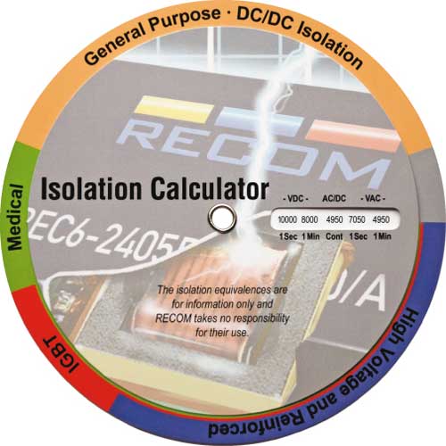
In conclusion, it is therefore recommended to choose an insulation voltage that is significantly above the expected voltage peaks. Combined with basic or even reinforced insulation, the reliability of IGBT converters can be greatly improved. The fact that manufacturers do not always provide the necessary information in the data sheets of their products can make it difficult for designers to compare like with like. Sometimes, the values refer to a test voltage applied for “1 second”. In other data sheets, the specifications apply to test voltages of “1 minute” or “continuous”. The longer the test time, the lower the voltage value. To enable users to determine the correct insulation value accurately, RECOM has developed a free insulation calculator (figure 4). It allows you to compare the ratings of different products at the click of a button.
Advanced IGBT converters from RECOM
In order to meet the demands of as many applications as possible, RECOM now offers seven new IGBT converter series. All models feature asymmetric outputs of +15V and -9V at input voltages of 5V, 12V, or 24V, respectively, and are therefore tailor-made for the operation of IGBT drivers. Special attention has been paid to the insulation rating of the new products. Ranging from 3kV (RH-xx1509D) to 6.4kV (RxxP1509D), the new converters offer suitable insulation values for virtually all applications. As designers often need to consider the size of components, the new IGBT converters are available with the compact SIP7 housing (RP-xx1509D), the universal DIP14 housing (RKZ-xx1509D), or as flat DIP24 miniature (RV-xx1509D) models.
These 1W and 2W modules are certified according to EN60950-1 and do not contain hazardous substances according to the RoHS2 and REACH Directives. As usual for RECOM devices, these products come with a three-year warranty.


