
ABSTRACT
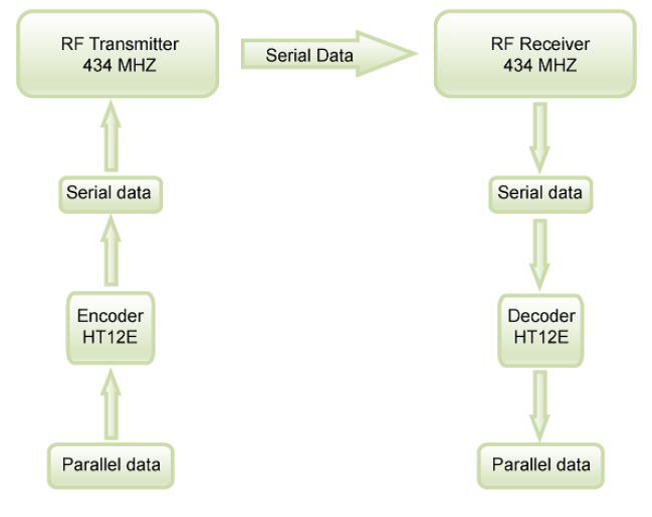
Using remote control for home appliances is a great choice. They can be used to on and off the appliances like TV, AC, DVD player, motor etc. with the help of our RF remote. This project utilizes the RF module (Tx/Rx) for making a wireless remote, which could be used to drive an output from a distant place. RF module, as the name suggests, uses radio frequency to send signals. These signals are transmitted at a particular frequency and a baud rate. A receiver can receive these signals only if it is configured for that frequency.
Whenever we are pressing any key in the remote it generates the corresponding RF signals, and these signals are received by the receiver unit. ASK transmitter and receiver is used as
Transmitter and receiver. HT12E, HT12D encoders and decoders are used in this electronic
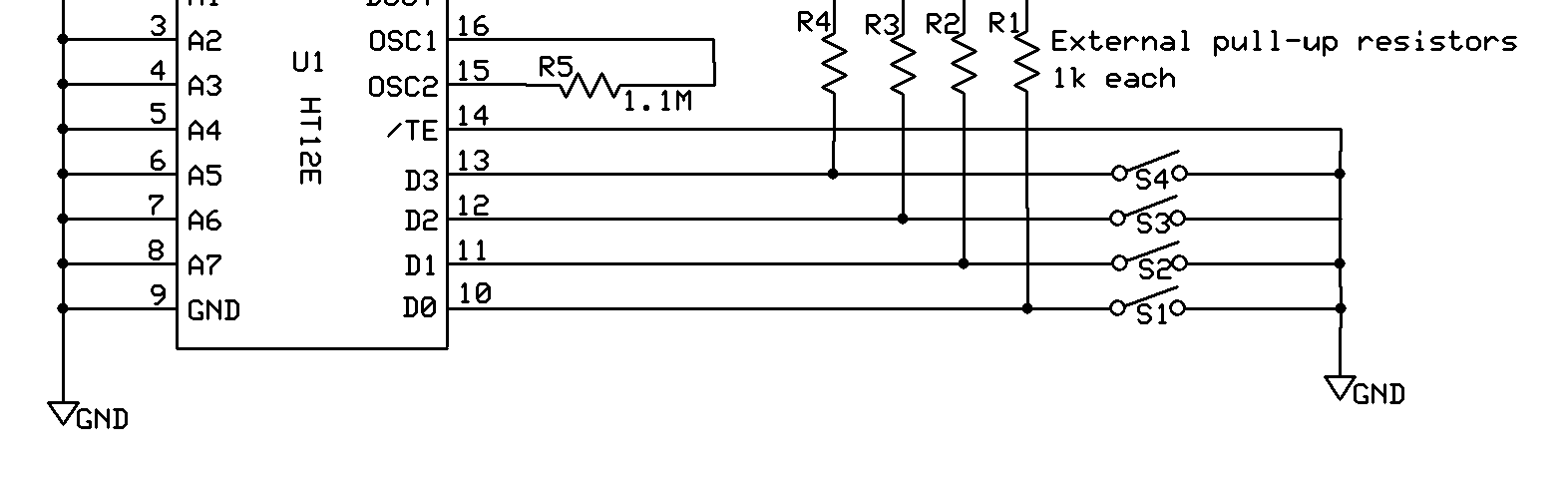
Circuit. A four channel encoder/decoder pair has also been used in this system. The input signals, at the transmitter side, are taken through four switches while the outputs are monitored on a set of four LEDs corresponding to each input switch.
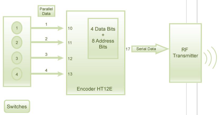
Encoder IC (HT12E) receives parallel data in the form of address bits and control bits. The
Control signals from remote switches along with 8 address bits constitute a set of 12 parallel
Signals. The encoder HT12E encodes these parallel signals into serial bits. Transmission is
Enabled by providing ground to pin14 which is active low.
The circuit can be used for designing Remote Appliance Control system. The outputs from the receiver can drive corresponding relays connected to any household appliance.
Introduction: In consumer electronics, a remote control is a component of an electronic device such as a television set, DVD player, or other home appliance, used to operate the device wirelessly from a short distance. Remote control is a convenience feature for the consumer, and can allow operation of devices that are out of convenient reach for direct operation of controls. Commonly, remote controls are Consumer IR devices which send digitally coded pulses of infrared radiation to control functions such as power, volume, tuning, temperature set point, fan speed, or other features. Remote controls for these devices are usually small wireless handheld objects with an array of buttons for adjusting various settings such as television channel, track number, and volume. For many devices, the remote control contains all the function controls while the controlled device itself has only a handful of essential primary controls. Earlier remote controls in 1973 used ultrasonic tones.
The remote control code, and thus the required remote control device, is usually specific to a
Product line, but there are universal remotes, which emulate the remote control made for most major brand devices. Remote control has continually evolved and advanced over recent years to include Bluetooth connectivity, motion sensor enabled capabilities and voice control. The earliest example of remote control by radio waves was developed in 1898 by Nikola Tesla. The first remote controlled model aero plane flew in 1932, and the use of remote control technology for military purposes was worked intensively during the Second World War, one result of this being the German Wasserfall missile. By the late 1930s, several radio manufacturers offered remote controls for some of their higher end models. Most of these were connected to the set being controlled by wires, but the Philco Mystery Control (1939) was a battery operated low frequency radio transmitter, thus making it the first wireless remote control for a consumer electronics device.
The circuit of this project utilises the RF module (Tx/Rx) for making a wireless remote, which could be used to drive an output from a distant place. RF module, as the name suggests, uses radio frequency to send signals. These signals are transmitted at a particular frequency and a baud rate. A receiver can receive these signals only if it is configured for that frequency. A four channel encoder/decoder pair has also been used in this system. The input signals, at the transmitter side, are taken through four switches while the outputs are monitored on a set of four LEDs corresponding to each input switch. The circuit can be used for designing Remote Appliance Control system. The outputs from the receiver can drive corresponding relays connected to any household appliance.
RF Communication:
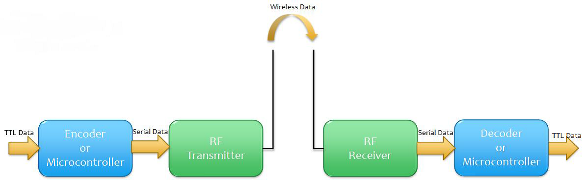
- Block diagram

RF itself has become synonymous with wireless and high-frequency signals, describing anything from AM radio between 535 kHz and 1605 kHz to computer local area networks (LANs) at 2.4 GHz. However, RF has traditionally defined frequencies from a few kHz to roughly 1 GHz. If one considers microwave frequencies as RF, this range extends to 300 GHz.
A general RF communication block diagram is shown above. Since most of the encoders/decoders/microcontrollers are TTL compatible, most of the inputs by the user will be given in TTL logic level. Thus, this TTL input is to be converted into serial data input using an encoder or a microcontroller. This serial data can be directly read using the RF Transmitter, which then performs ASK (in some cases FSK) modulation on it and transmit the data through the antenna. The transmitter module takes serial input and transmits these signals through RF. The transmitted signals are received by the receiver module placed away from the source of transmission.
The signals are transmitted at a particular frequency and a baud rate. A receiver can receive these signals only if it is configured for that frequency. At the receiver side, the RF Receiver receives the modulated signal through the antenna, performs all kinds of processing, filtering,
Demodulation, etc. and gives out a serial data. This serial data is then converted to a TTL level logic data, which is the same data that the user has input.
Block diagram:
 The above shown is a block representation of the circuit going to be built. The data to be sent will be in the form of TTL logic as most the digital systems work on it. Hence in order to convert the data in logic from to a serial form, the encoder IC is to be used. This encoder provides a facility of sending lot of data through a single channel by making use of the address bits.
Data can be sent by providing specific address at the input side. On the receiver side, the data received in the form of serial data is again to be converted into the digital form which is done by Decoder IC. In order to get the data correctly the address provided at the input side is to be put at the receiver side also. This will provide a secured wireless communication.
The circuit holds good up to a range of 400mts. behind the specified range, the circuit may not work properly as per the design aspects.
Circuit Diagram
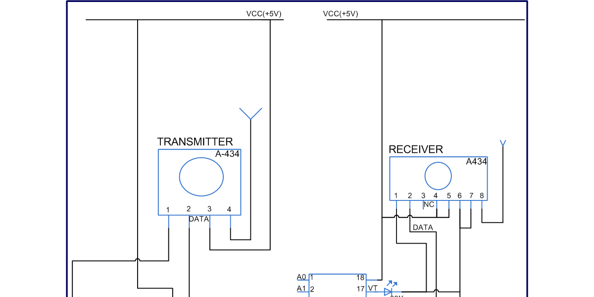
 Transmitter:


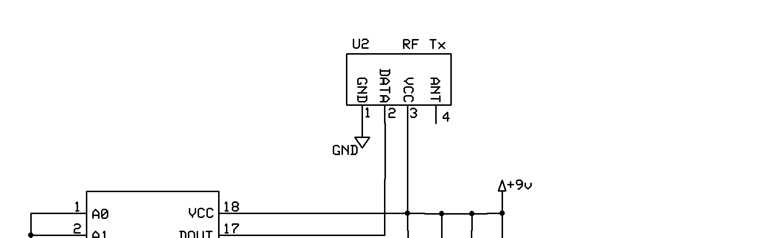
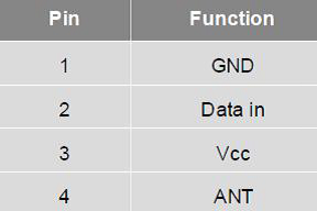
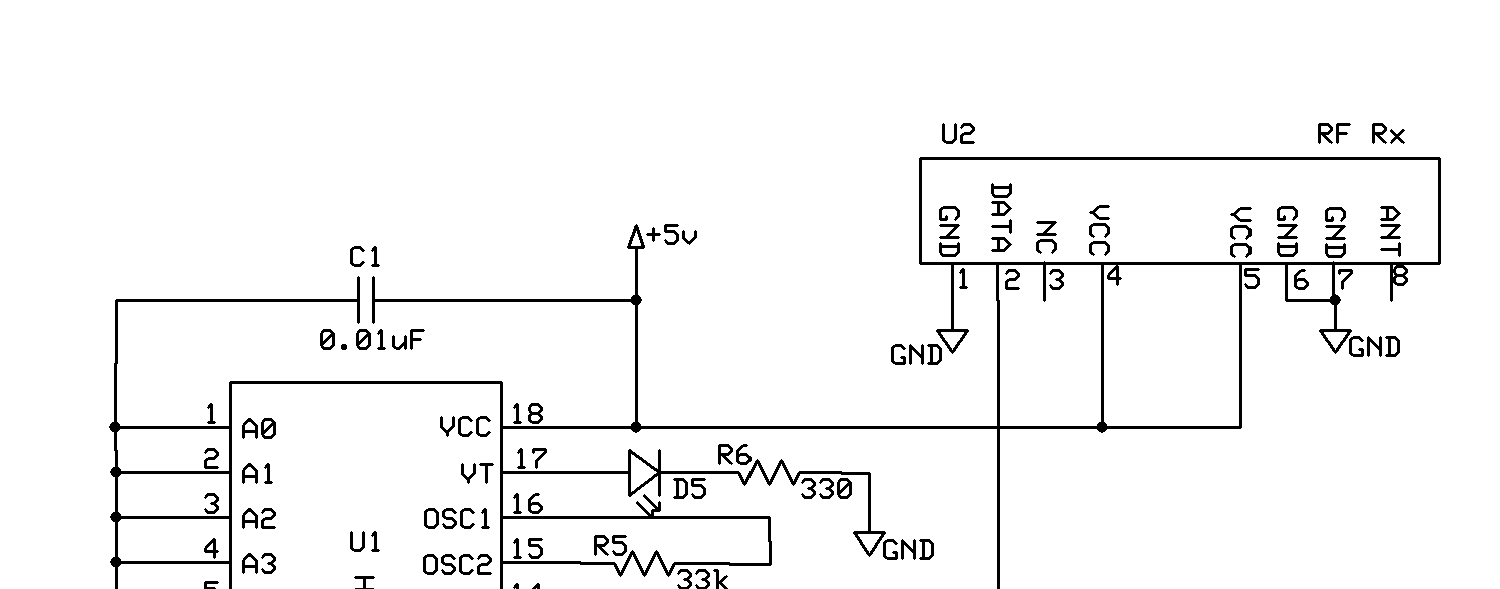
This simple RF transmitter, consisting of a 434MHz license-exempt Transmitter module and an encoder IC, was designed to remotely switch simple appliances on and off. The RF part consists of a standard 434MHz transmitter module, which works at a frequency of 433.92 MHz and has a range of about 400m according to the manufacture. The transmitter module has four pins. Apart from “Data” and the “Vcc” pin, there is a common ground (GND) for data and supply. Last is the
RF output (ANT) pin.
Transmitter Circuit
 To mount the antenna (aerial) as close as possible to pin 4 (ANT) of the transmitter module. Note that, for the transmission of a unique signal, an encoder is crucial. For this, we have used the renowned encoder IC HT12E. HT12E is capable of encoding information which consists of N address bits and 12N data bits. Each address/ data input can be set to one of the two logic states.
The programmed addresses/data are transmitted together with the header bits via an RF transmission medium upon receipt of a trigger signal. Solder bridges TJ1 and TJ2 are used to set the address and data bits. The current consumption with a supply voltage of near 5.4V is about 10 mA. Since the current consumption is very little, the power can also be provided by standard button cells. Recommended antenna length is 17 cm for 433.92 MHz, and a stiff wire can be used as the antenna.
Receiver:
This circuit complements the RF transmitter built around the small 434MHz transmitter module. The receiver picks up the transmitted signals using the 434 MHz receiver module. This integrated RF receiver module has been tuned to a frequency of 433.92MHz, exactly same as for the RF transmitter. The miniature 434MHz RF receiver module receives On-Off Keyed (OOK) modulation signal and demodulates it to digital signal for the next decoder stage. Local oscillator is made of Phase Locked Loop (PLL) structure.
 Component Description:


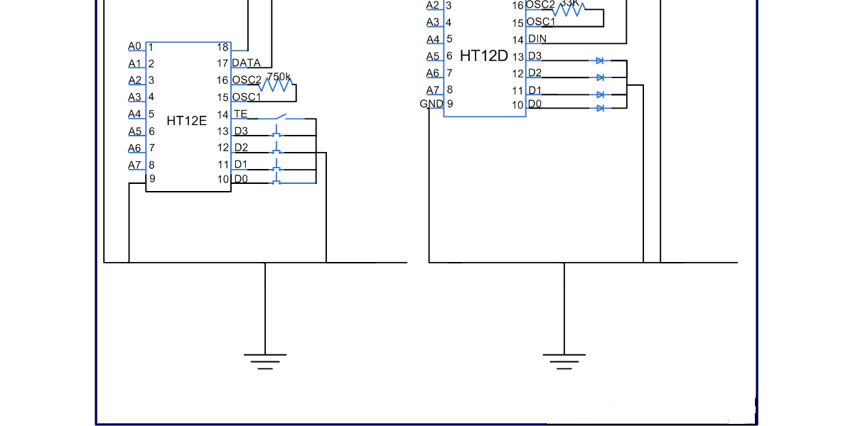
HT12E- Encoder
 The HT12E Encoder ICs are series of CMOS LSIs for Remote Control system applications.
They are capable of Encoding 12 bit of information which consists of N address bits and 12-N data bits. Each address/data input is externally trinary programmable if bonded out.
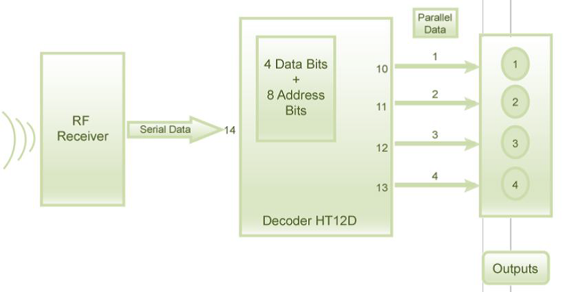
This IC is mainly used to interface RF and IR circuits. This IC converts 12 bit parallel to serial. These 12 bits are divided into 4 data bits and 8 address bits. This IC has transmitter enable pin. When trigger signal is received on this pin, the address and data bits are transmitted together. HT12E starts a 4 word transmission cycle upon receipt of enable. The transmission cycle is repeated till transmitter enable is kept low. As soon as TE returns to high, the encoder output completes its final cycle and then stops.
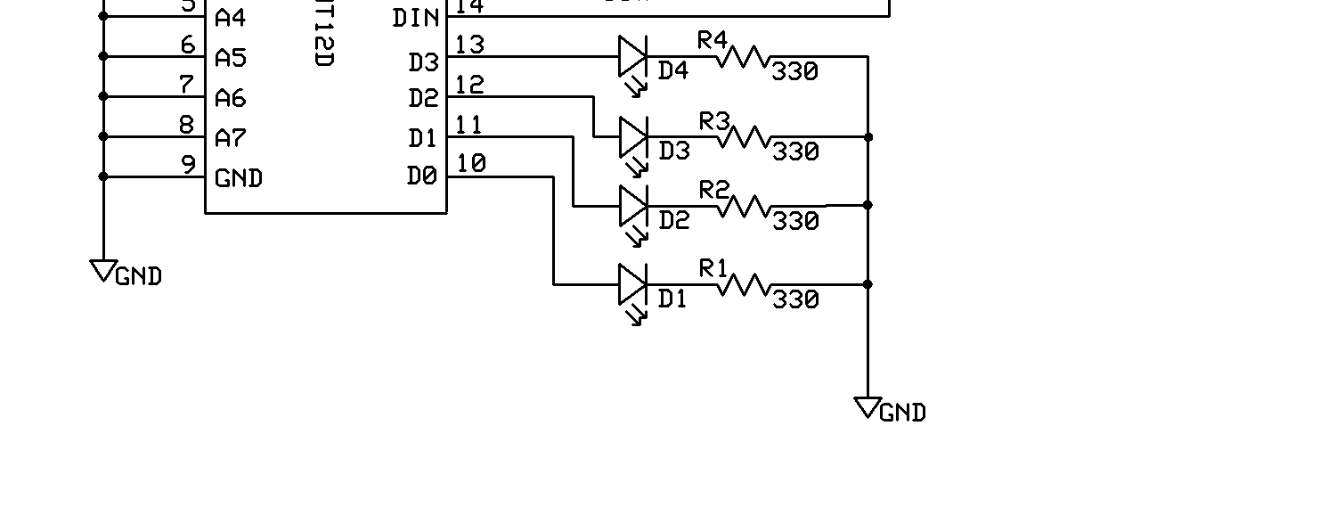
HT12D – Decoder
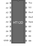 The HT12D Decoder ICs are series of CMOS LSIs for remote control system applications. This ICs are paired with each other. For proper operation a pair of encoder/decoder with the same number of address and data format should be selected. The Decoder receive the serial address and data from its corresponding encoder, transmitted by a carrier using an RF transmission medium and gives output to the output pins after processing the data.
This decoder IC converts serial input data to parallel. This IC indicates valid transmission by a high at VT (Valid Transmission) pin.HT12D is capable to decode 12bit data (8 address bits and 4 data bits). The output data remains unchanged till the new data is received. It is mainly used in RF and IR circuits.
These decoders are mainly used for remote control applications like burglar alarm, car door alarm, security system etc. The chosen pair of encoder and decoder for communication should have same number of address and data bits. The data on 4 bit latch type output pins remain unchanged until new is received.
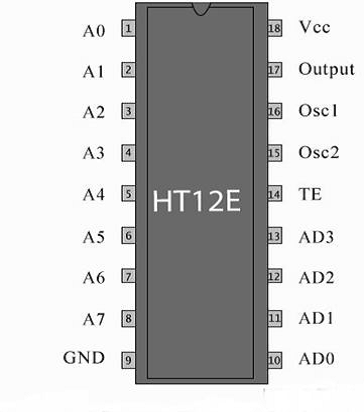
| PIN NO. | Function | Name |
| 1 | 8 bit Address pins for input | A0 |
| 2 | A1 | |
| 3 | A2 | |
| 4 | A3 | |
| 5 | A4 | |
| 6 | A5 | |
| 7 | A6 | |
| 8 | A7 | |
| 9 | Ground (0V) | Ground |
| 10 | 4 bit Data/Address pins for input | AD0 |
| 11 | AD1 | |
| 12 | AD2 | |
| 13 | AD3 | |
| 14 | Transmission enable; active low | TE |
| 15 | Oscillator input | Osc2 |
| 16 | Oscillator output | Osc1 |
| 17 | Serial data output | Output |
| 18 | Supply voltage; 5V (2.4V-12V) | Vcc |
Operation:
Encoder IC (HT12E) receives parallel data in the form of address bits and control bits. The control signals from remote switches along with 8 address bits constitute a set of 12 parallel signals. The encoder HT12E encodes these parallel signals into serial bits. Transmission is enabled by providing ground to pin14 which is active low. The control signals are given at pins 1013 of HT12E. The serial data is fed to the RF transmitter through pin17 of HT12E.
Transmitter, upon receiving serial data from encoder IC (HT12E), transmits it wirelessly to the RF receiver. The receiver, upon receiving these signals, sends them to the decoder IC (HT12D) through pin2. The serial data is received at the data pin (DIN, pin14) of HT12D. The decoder then retrieves the original parallel format from the received serial data. When no signal is received at data pin of HT12D, it remains in standby mode and consumes very less current (less than 1μA) for a voltage of 5V.
When signal is received by receiver, it is given to DIN pin (pin14) of HT12D. On reception of signal, oscillator of HT12D gets activated. IC HT12D then decodes the serial data and checks the address bits three times. If these bits match with the local address pins (pins 18) of HT12D, then it puts the data bits on its data pins (pins 1013) and makes the VT pin high. An LED is connected to VT pin (pin17) of the decoder. This LED works as an indicator to indicate a valid transmission.
This radio frequency (RF) transmission project employs Amplitude Shift Keying (ASK) with
Transmitter/receiver (Tx/Rx) pair operating at 434MHz. The transmitter module takes serial input and transmits these signals through RF. The transmitted signals are received by the receiver module placed away from the source of transmission. The system allows one way
Communication between two nodes, namely, transmission and reception.
The RF module has been used in conjunction with a set of four channel encoder/decoder ICs.
Here HT12E & HT12D have been used as encoder and decoder respectively. The encoder converts the parallel inputs (from the remote switches) into serial set of signals. These signals are serially transferred through RF to the reception point. The decoder is used after the RF receiver to decode the serial format and retrieve the original signals as outputs. These outputs can be observed on corresponding LEDs.
 The corresponding output is thus generated at the data pins of decoder IC. A signal is sent by lowering any or all the pins 1013 of HT12E and corresponding signal is received at receiver’s end (at HT12D). Address bits are configured by using the by using the first 8 pins of both encoder and decoder ICs. To send a particular signal, address bits must be same at encoder and decoder ICs. By configuring the address bits properly, a single RF transmitter can also be used to control different RF receivers of same frequency.
To summarize, on each transmission, 12 bits of data is transmitted consisting of 8 address bits and 4 data bits. The signal is received at receiver’s end which is then fed into decoder IC. If address bits get matched, decoder converts it into parallel data and the corresponding data bits get lowered which could be then used to drive the LEDs. The outputs from this system can either be used in negative logic or NOT gates can be incorporated at data pins.
The Block diagram representing the transmission and reception of data is shown in the below figure.
Transmission Process
 Reception Process

 Circuit Application:

This RF remote control circuit is now extended in order to develop an application. A remote controlled has been made which can be controlled by using this operation of the circuit. Atmega8 Microcontroller is used to build the structure of the robot.
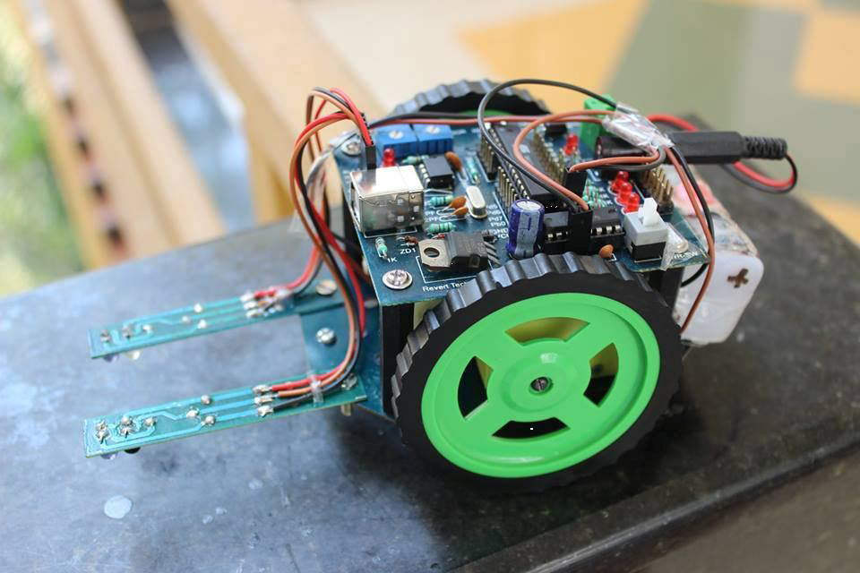 In today’s age, the robotic industry has been developing many new trends to increase the efficiency, accessibility and accuracy of the systems. Basic tasks could be jobs that are harmful to the human, repetitive jobs that are boring, stressful etc. Though robots can be a replacement to humans, they still need to be controlled by humans itself. Robots can be wired or wireless, both having a controller device.
The advance of robotic technology will bring ease to human life not only in the industrial sector but also the education and entertainment sector. In this research, an idea of a robot that can be controlled by remote is proposed. The classification process depends on several sensors such as light sensor, color sensor, and touch sensors. Service robots directly interact with people, so finding a more natural and easy user interface is of fundamental importance. While earlier works have focused primarily on issues such as manipulation and navigation in the environment, few robotic systems are used with user friendly interfaces that possess the ability to control the robot by natural means.
Applications:
- Burglar Alarm, Smoke Alarm, Fire Alarm, Car Alarm, Security System
- Garage Door and Car Door Controllers
- Cordless telephone
- Other Remote Control System
- Industry and garage
- Military
- Video games and computers
- Photography
- Standby Power Consumption
Advantages:
1 Spying on people in ways people can’t move and from views humans can’t reach.
2 Going far down into the unknown waters where humans would be crushed.
3 Giving us information that humans can’t get.
4 They can perform tasks faster than humans and much more consistently and accurately.
5 They can capture moments just too fast for the human eye to get, for example the Atlas detector in the LHC project can capture ~ 600000 frames per second while we can see at about 60.
Conclusion:
Our design turned out to be approximately what we expected. As mentioned before, we had planned to build our own solder-board circuit so that the remote control was truly not attached to any strings or wires. That aside, our code was implemented as designed, with some small modifications along the way. As mentioned before, our remote control worked for the standard that we tested it on. We are working on the progress of the project by implementing the wireless control using Gestures.


