The robot is controlled using Web Server and ZigBee Communication.
A robot is electro-mechanical machines which is generally control and guided by computer or electronic programming and is thus able to do tasks.Robots are outfitted with wide reaches and slim arms, steady repeatability and precise tooling-all, of which allows them to be extremely accurate. This high precision capability makes them a good match for pick and place application. Controlling robotic arm wirelessly is very helpful for a wide range of applications ranging from industrial to medical fields. The aim of this project is to develop a robotic arm which should be controlled by an authorized person at any time and from any place using the web technology. The robot is controlled by two methods, one through local system which has zigbee and the other through the web server which allows the client to access the robot from anywhere in the world. So the main advantage of our project is that there is no any limited distance is needed for running the robot.
Why Robots?
Earlier we use human power for defusing the bomb and changing the cadmium rods in atomic power plant, which is very dangerous for human life and leads to the human hazard because developed suit for preventing the radiation of radioactive substances are not powerful and not prevent more than an hour. This leads to the less work efficiency and increases the risks. For avoiding this types of problem in the nuclear power plant. The additional features of this project are that the robot is controlled by web server. If the technician is not present in the power plant then no need to worry he can access the robot from his home or anywhere in the world which saves the travel expenses and time. We use our robot it uses its hands and picks the bomb and carries to safe place. If anything happen in between the replacement of bomb there will be no human hazard initiated. Our robot consists of DC geared motor which helps in smooth moving of hands and provides proper control on the robot movement. This project is developed for the helping of humans and reducing the risks of their lives. For working of this project internet connection is needed and a server pc must be run on the host side to which client can access for anywhere in the world. He should only enter the IP address of the host and pass through the authentication process and then he can control the robot .
Architecture at robotic side

Hardware Architecture at Server Side
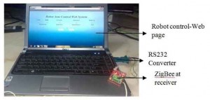
In this project ZigBee at local system connected via serial port with RS232 converter. The architecture of ZigBee connection to PC is given in figure 2. The local system controls the robotic arm and wheel movement through wireless ZigBee communication.


The communication between Local system and client system has been communicated through web server. All the data are sent to the web server through local system and the clients can easily access the information from the server. Zigbee is mainly act as wireless communication between robot and the local system and uploads the data to the web server. The local system must be in the range of the zigbee module then only it can easily communicates the data to the local system and also to the server.
Hardware Design
AT89s52 Microcontroller
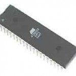
The AT89S52 is a low-power, high-performance CMOS 8-bit microcontroller with 8Kbytes of in-system programmable Flash memory. The device is manufactured using Atmel‟s high-density non-volatile memory technology and is compatible with the industry-standard 80C51 instruction set and pin out. The on-chip Flash allows the program memory to be reprogrammed in-system or by a conventional non-volatile memory programmer. The Atmel AT89S52 is a powerful microcontroller which provides a highly-flexible and cost-effective solution to many embedded control applications. Figure 4 shows structure of the Microcontroller.
DC Motor

A DC motor is an electric motor that runs on direct current (DC) electricity. DC motors were used to run machinery, often eliminating the need for a local steam engine or internal combustion engine. DC motors can operate directly from rechargeable batteries, providing the motive power. Figure 5 shows DC geared motor Structure.
IR Sensor
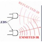
IR Sensor is an electronic device that emit and/or detects infrared radiations in order to sense object of its surrounding. It can measure the heat of an object as well as detect motion. All object emit the thermal radiation which is invisible to our eyes, but can be detected by an IR sensor that accept and interprets it.IR sensor devices detect infrared wavelengths, or light made up of electronic radiation with a wavelength between 0.7 to 1000 microns, a system of measurement equal to one millionth of a meter. This wavelength range makes up the infrared band, which emits radiation temperatures detectable by IR sensor. The detectors convert the IR energy into an electrical signal, which then is converted into a temperature value based on the object’s emissivity. This value may be displayed on the IR sensor or converted as digital input and sent to a computer terminal for display. Figure 6 shows the Object detecting procedure and Figure 7 shows the flowchart of IR sensing, Figure 8 shows the IR Module.


ZigBee
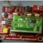
ZigBee and IEEE 802.15.4 are standards-based protocols that provide the network infrastructure required for wireless sensor network applications. 802.15.4 defines the physical and MAC layers, and ZigBee defines the network and application layers. For sensor network applications, key design requirements revolve around long battery life, low cost, small footprint, and mesh networking to support communication between large numbers of devices in an interoperable and multi-application environment. This zigbee will be low cost, more secure, reliable, low power consumption. And the module is shown in the figure 9.
Relays

A relay is an electrically operated switch. Current flowing through the coil of the relay creates a magnetic field which attracts a lever and changes the switch contacts. Relays are used where it is necessary to control a circuit by a low-power signal (with complete electrical isolation between control and controlled circuits), or where several circuits must be controlled by one signal. The first relays were used in long distance telegraph circuits, repeating the signal coming in from one circuit and re-transmitting it to another. Relays allow one circuit to switch a second circuit which can be completely separate from the first. Figure 10 shows the switching concept of relay.
Rs232

As shown in figure 11, RS-232 devices may be classified as Data Terminal Equipment (DTE) or Data Circuit-terminating Equipment (DCE); this defines at each device which wires will be sending and receiving each signal. The standard recommended but did not make mandatory the D-subminiature 25 pin connector. In general and according to the standard, terminals and computers have male connectors with DTE pin functions, and modems have female connectors with DCE pin functions. Other devices may have any combination of connector gender and pin definitions. Many terminals were manufactured with female terminals but were sold with a cable with male connectors at each end; the terminal with its cable satisfied the recommendations in the standard.
The 9 pin DE-9 connector was used by most IBM-compatible PCs since the IBM PC AT, and has been standardized as TIA-574. More recently, modular connectors have been used. Standard EIA/TIA 561 specifies a pin assignment, 10P10C connectors can be found on some devices as well. Digital Equipment Corporation defined their own DEC connect connection system which was based on the Modified Modular Jack (MMJ) connector.
RS 232 Converter
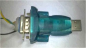
By using a microcontroller with hardware implemented USB interface. It is necessary to know how USB works and write firmware into the microcontroller accordingly. Additionally, it is necessary to create a driver on the computer side, unless if the operating system includes standard USB classes. The main disadvantage is the lack of availability of this kind of microcontrollers and their high price compared to simple “RS232” microcontrollers and the RS232 convertor is shown in the figure 12.
Software
Embedded C
During infancy years of microprocessor based systems, programs were developed using assemblers and fused into the EPROMs. There used to be no mechanism to find what the program was doing. LEDs, switches, etc. were used to check correct execution of the program. Some “very fortunate‟ developers had In-circuit Simulators (ICEs), but they were too costly and were not quite reliable as well. As assembly language programs are specific to a processor, assembly language didn’t offer portability across systems. To overcome this disadvantage, several high level languages, including C, came up. Some other languages like PLM, Modula-2, Pascal, etc. also came but couldn’t find wide acceptance. Amongst those. Due to the wide acceptance of C in the embedded systems, various kinds of support tools like compilers & cross-compilers, ICE, etc. came up and all this facilitated development of embedded systems using C. Here we using keil cross compiler to burn the source code to controller.
Compiling and Burning Procedures
Step 1: Create new project
Step 2: Select the device for the Target
Step 3: Add files to the source
Step 4: Build and Link the target program
Step 5: Compile and Debug the program
Step 6: Create Hex file from the source file
Step 7: Download the Hex file using willar programmer
Step 8: Hex file downloaded in to the AT89C51 successfully
Web server
Visual Studio 2005
Visual Studio 2005 was upgraded to support all the new features introduced in .NET Framework 2.0, including generics and ASP.NET 2.0. The feature in Visual Studio was upgraded for generics and new project types were added to support ASP.NET web services. Visual Studio 2005 also includes a local web server, separate from that can host ASP.NET applications during development and testing. It also supports all Sql Server 2005 databases. Database designers were upgraded to support the ADO.NET 2.0. And figure 13 shows the server controlling page on Host system.
IIS (Internet Information Service)
Internet Information Server (IIS) is a World Wide Web server, a Gopher server and an FTP server all rolled into one. IIS means that you can publish WWW pages and extend into the realm of ASP (Active Server Pages) whereby JAVA or VBscript (server side scripts) can generate the pages on the fly. There are two ways of using IIS. First one is ask for proposal on appropriate technology and business plan. The second is making proposal for the publication on IIS homepage. Everyone can get access the homepage anytime. Without any charges any one can make proposal. We can select any need from the home page and send the proposal to IIS with the help of input form that is also available on home page. The proposed idea is opened after confirmation from the IIS but name of the applicant is not disclosed. IIS have all the rights to reform the proposal. The secrecy is necessary for you own security. IIS also receive 50,000 YEN from owner and from the person who makes proposal. IIS take fee from the regular members and special members.

Implementation

Automatic Mode

As per figure 15 shows the Robot controls in web server and this automatic mode is satisfy to working the robot movement. In automatic mode the robot is moved without any restriction if any obstacle comes in front of this robot, it turns right side direction automatically[5,6]. In this mode there is no movement in robotic arm. It is designed only for safety of robot to save it from damage [11, 12]. In this mode there is no connection between server and client. Figure 16 shows the robotic movement in automatic mode.
Manual mode

In manual mode the robot is controlled through the web server. In this mode the server sends the data to robot through ZigBee also it receives the data from server through ZigBee. The control page is created through the ASP .Net for controlling the robot. In this mode the robot move any direction regarding by user directions. The robotic arms pick and release any object which is in front of the robot Fig. 17 shows the flow chart of manual mode. And figure 18 shows Object picking procedure.

Conclusion
Today we find most robots working for industries, factories, warehouses, and laboratories. Robots are useful in many ways. In this project robot is controlled by web server which is a useful technique. Having a robot with this type of capabilities provides a lot of benefits such as we can access the robot from anywhere in the world. Using this concept we can save our time and money for travelling here and there, that is we can access the robot from house, office and so on. The future enhancement in our project is that we can add camera to the existing robot for getting access in non-visible area and hence the robot can also be work as a spy robot that can be used for those area where human ca


