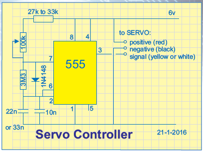
This project will open and close something remotely. It could be a door-latch or the points on a model railway. Or it can turn something ON and OFF.
The project uses a SERVO (see photo) and this has been widely used in remote control projects such as cars and planes to activate the steering or the flaps on the wings.
They are a very clever item, consisting of a motor and gearbox with a lot of electronics so you can control the output shaft very accurately with clockwise or anticlockwise movement. And they are very cheap.
 Normally an arm (called a lever or crank) is connected to the shaft so the rotational movement can be converted to linear motion. Each servo comes with a range of levers (called “horns”) to do all sorts of things. You can even make interesting toys and simple robotic activations.
In most cases a signal is sent from a transmitter to a receiver to activate these servo’s but we are going to use it in a simple situation, using 3 wires or “lines” to achieve the activation we need.
This project is ideal for beginners as it uses a servo and a simple 555 circuit with all components easy to obtain from electronics and hobby stores.
But first you have to think of a use. It might be to adjust the angle of a solar panel or unlock a front door or control the movement of a security camera.
Most servos rotate about 270 degrees and when an arm is connected, it will produce a push or pull via a connecting rod to provide LINEAR MOTION (linear activation).
Normally, a servo moves from one position to another very quickly, but our circuit uses a pot (potentiometer) and you can control the “speed” at which the shaft rotates.

We also have a circuit using push buttons and these can be labelled up, down or on, off to let you know what will happen at the other end. The buttons simply rotate the shaft quickly from one extreme to the other.
Servos come in many different sizes and the larger ones are more powerful, but they all respond to the same signals and only 3 wires are needed. The red wire is supply (6v), black wire is 0v and yellow is “signal”. The maximum voltage is 6v and the servo will work down to 4.5v.
The “signal” is a set of pulses and the number of cycles depends on how long the button is pressed. The number of cycles simply keeps the servo operating until the desired position is reached. It is the width of the HIGH that creates the “end point” and you keep delivering the signal until the end point is reached.
The signal is called PULSE CODED MODULATION and the HIGH will vary from 0.5mS to 2.5mS. The LOW time needs to be about 20mS. This means the coded signal arrives at about 50 cycles (50 times) per second (50Hz).
When you push one of the buttons, the HIGH may not match the HIGH produced by the pot connected to the shaft inside the servo. The electronics drives the motor to rotate the shaft until the two HIGHs are the same width.
If you produce a HIGH that represents the shaft fully clockwise, the motor will rotate the shaft fully clockwise and you need to keep delivering the HIGHs until the servo has reached the required position. By turning the pot slowly, the servo reaches the desired position very quickly and turns off the motor and “waits.” If you turn the pot a little bit more, the motor keeps up with the pot and output rotates slowly. This is how you can get a realistic action such as a mouth moving or a similar animation.
The value of the components will have to be adjusted to suit your servo so the motor stops at the end of rotation and does not keep “hunting.”
You can use a push button on the supply so the circuit is only active when needed.
A small PCB is available from Colin Mitchell.
Enquiries about the circuit can be sent to Colin Mitchell:


