Carmelo BATTAGLIA, Technical Marketing Engineer, Asia Region, STMicroelectronics
 The Global Smart Home market is expected to reach around 97B$ before the finish of 2025; main application categories are represented from Security Management, Energy and resource management, Convenience and comfort, Health and wellness management and Media Entertainment.
Inside the home multiple kinds of energy remain normally unused: Light, temperature differences, Motor mechanical vibration, Doors and windows movement; nowadays these harvest energy can be utilized thanks to Photovoltaic cell, thermoelectric element, piezoelectric generator, other.
STMicroelectronics offers different power management devices that match many requirements of these sources. As a typical application, we will consider a photovoltaic harvest system; see Fig.1, a block diagram of a General Harvest application.
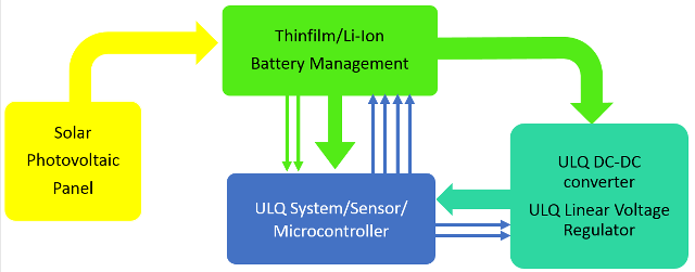 Figure1: General Harvest Block diagram (Photovoltaic Source with Energy Storage)
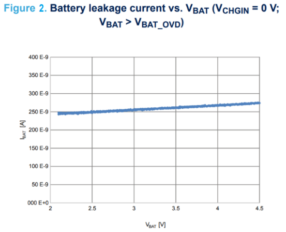
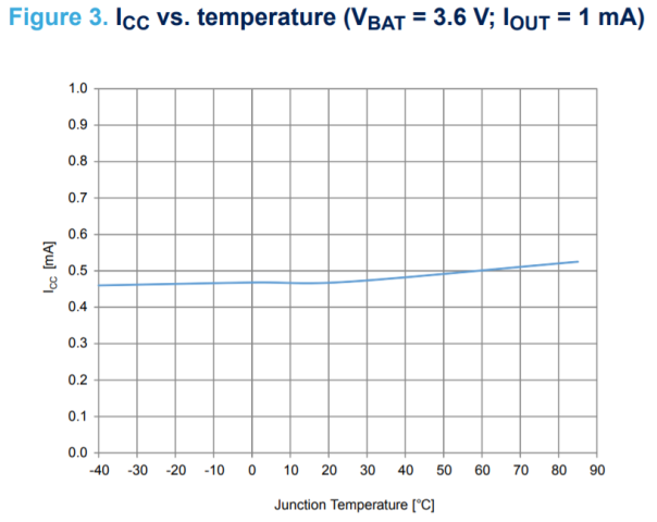
Photovoltaic energy is limited during the day, unregulated, and mainly concentrated during the time of morning light; for this reason, it should be used as best as possible with high efficiency converter to supply the system or stored inside a main Li-ion battery for later usage. STMicroelectronics’ new battery management STBC15 series can manage the charge of battery every time the source voltage is higher than the battery level as well as supply the system at the same time. This is accomplished with an internal power path MOSFET, which automatically provides the battery energy to the system and simultaneously recharges the LI-ion battery when a valid source is available. The ultra-low power architecture allows the STBC15 to consume less than 250 nA from the battery (see figure 2) when the input power source is removed, and only 0.48 µA supply current (see figure3) will be used to control the charging phase when a source is available.
 In this way, almost all the source energy available will be stored inside the battery. The ultra-low quiescent battery management embeds digital controls (1.8V compatible GPIOs) to set one of the four programmable battery floating voltages, battery overcurrent threshold among four different current levels, and provide a real time input and battery monitor flags. More details can be found at the product home page: www.st.com/battery-chargers.
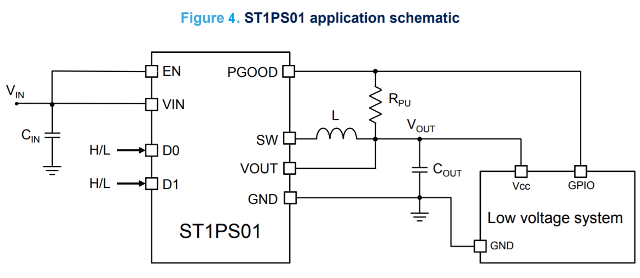
In order to optimize the battery-stored energy or to use direct source generated from a photovoltaic cell, STMicroelectronics recommends designing the harvest system using a very low quiescent current switching converter. The most recent product available on the market is the Nano-quiescent buck ST1PS01 series. It is a miniaturized synchronous step-down converter, which is able to provide up to 400 mA output current with an input voltage ranging from 1.8 V to 5.5 V. This converter is specifically designed for applications where high efficiency, PCB size, and thickness are the key factors. The output voltage can be set using two digital control inputs (D0, D1) and a VOUT from 0.6 V to 3.3 V can be dynamically programmed. A typical application schematic is shown in figure 4. With its enhanced PCC (peak current control loop), the ST1PS01 reaches very high efficiency conversion using just a 2.2 µH inductor (L) and two small capacitors (CIN and COUT).
 Advanced design circuitry is implemented to minimize the quiescent current, just 500nA during no load standby conditions, and as a result, the overall harvesting system operating time will be extended as long as possible while waiting next battery recharge event. More technical details can be found at this link: www.st.com/dcdc.
If necessary, an additional low current voltage rail can be generated using STMicroelectronics’ ultra-low quiescent current linear voltage regulator STLQ020 series. The STLQ020 is a 200 mA low-dropout voltage regulator, able to work with an input voltage ranging from 2 V to 5.5 V. The typical dropout voltage at maximum load is 160 mV. The ultra-low quiescent current, which is just 300nA at no load, extends the battery life of harvesting systems. See figure 5 for a graph showing the STLQ020 quiescent current behavior temperature dependence.
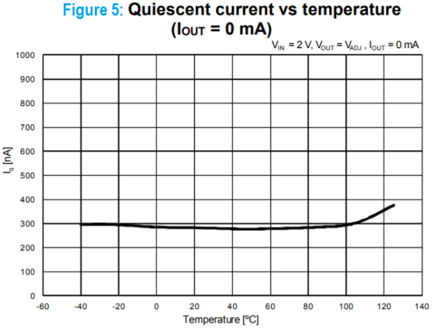 Despite the ultra-low consumption design, the STLQ020 is able to provide a fast transient response and good PSRR performance due to its adaptive biasing circuit. When the voltage rail and the harvest subsystem is not used, the STLQ020 can be set in shutdown mode by enable pin input, reducing total current consumption to 1 nA.
The STLQ020 is also designed to keep the quiescent current under control and at a low value during dropout operation, which helps to extend the operating time of battery-powered devices even more. It also includes short-circuit constant-current limiting and thermal protection, and a choice of several small packages are available.
More details can be found at the product home page: www.st.com/ldo.
In table1, we highlight a tailored products selection that could be used to design a harvesting system or a portable high efficiency application. It ranges from just a few mA current capability up to more than 1A, depending on the final application requirements and the battery capacity selected. The discussed applicable devices are detailed in bold font.
| Function | Max current capability | ||||||
| >1A | 800mA | 650mA | 450mA | 250mA | 150mA | 40mA | |
| Battery charger IC | L6924 | STBC08 | STBC03 | STBC02 | STNS01 | STBC15, STBC15L | |
| RGB LED Driver | = | LED1202 12ch | STP4CMP
4ch |
||||
| Low Quiescent LDO | LD39100 | LD39050 | STLQ020, LD39130S | STLQ015, LDBL20 | STLQ050, ST715 | ||
| Low Quiescent Buck | L6986/86F | L6985F | ST1PS01 | ||||
| Low Quiescent Buck-boost | = | STBB2 | |||||
| STBB1A, STBB3J | |||||||
Table 1: Recommended Power Management lineup for Harvesting Systems
In case the harvest system requires an operating voltage rail higher than the minimum battery voltage cut-off (typically 2.8V), the low quiescent current buck-boost converter STBB series could be used to generate the requested fixed rail from every battery condition: even a fully charged battery 4.2V-4.35V level, or worst case, fully discharged level 2.6-3.0V (see figure 6).
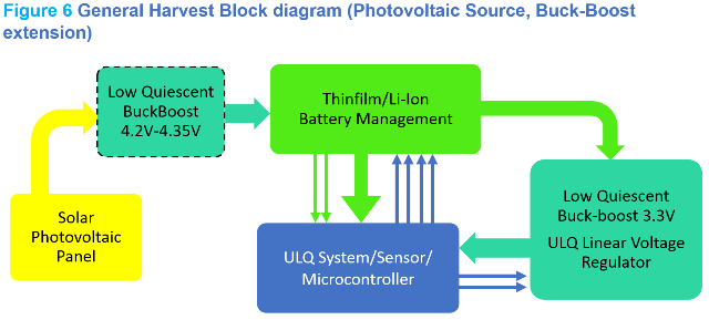 The high efficiency of STMicroelectronics buck-boost converter STBB series and its extended operative input supply range, enables the harvest system to store in the battery more energy generated from the photovoltaic panel source. With the minimum voltage of 1.8V, the buck-boost converter is able to generate a high enough voltage to recharge the Li-Ion single cell battery. Figure 7 illustrates the typical buck-boost efficiency at different input and output voltages.
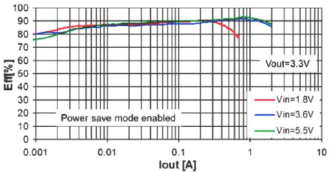 Figure 7: Low Quiescent buck-boost converter typical efficiency performance
Other complementary optional function such as an RGB LED Driver could be add to the harvesting system to simplify and attractively implement the graphical user interface communication (GUI). ST’s LED1202, I2C standard interface 12-channel LED driver, represents the new STMicroelectroncis product line that will reach the mass production by Q1.2019.Figure 8 shows a general electric schematic for this sub-section. The LED1202 is designed to reduce the current consumption down to 5 µA during off mode, guarantee high accuracy led current control up to +-1%, and implements special features like phase shifting to reduce inrush current, including automatic sequencing without microcontroller intervention through 8 programmable patterns and up to 12-bit local PWM resolution.
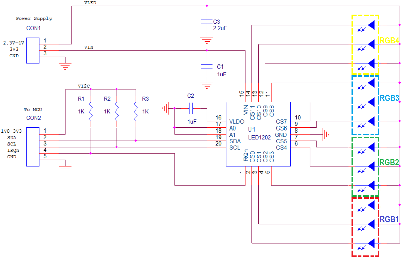 Figure 8: RGB Led Driver General electrical schematic (up to 4-RGB led driving)
More details can be found at the product’s home page: www.st.com/led or by contacting your local STMicroelectronics sales office.


