Mark Patrick, Mouser Electronics
DC-DC converters are now widely used to convert one voltage to another. In order to use them, it is desirable for designers to understand their operation and how to select them for a given application. This article provides an overview of DC-DC conversion including examining some of the main technical challenges in creating a compact and reliable solution. It will also help designers interpret manufacturers’ data, allowing them to select the correct solution for an application.
Volta experimented with copper, zinc and damp cardboard to produce the first battery, although there was nothing that required DC to run at the time. The main applications were things like lighting, and AC was fine for that, with voltages being changed via transformers where necessary.
As technology developed, it was discovered that, unlike AC, DC could be stored in batteries or capacitors. This proved useful when the telephone was invented. There was no particular DC-DC conversion technology at the time, but voltages could be created by combining battery cells as needed.
However, there were practical limits to this approach and, when technologies such as vacuum tubes emerged, voltages in the region of 150V were required. To address this need, engineers began to consider how circuits could be constructed to change voltage levels, leading to early DC-DC converters.
Modern DC-DC conversion
There are many types and configurations of DC-DC converters, and they can be categorized by their structure and function. Some provide galvanic isolation while others are non-isolated; some increase the voltage (stepup) while others reduce it (step down) ,and others have the capability to do both. There are many types and power levels available, and through increasing commonality of footprints, products from different manufacturers are easily interchanged.
In DC-DC converter terms isolation simply means that there is no connection between the input and output. This usually implies the inclusion of a transformer which defines and provides the isolation boundary. In this type of converter, the output is often termed “floating,” meaning that it can be configured to be positive or negative with respect to the input.
Isolation is also important in terms of achieving certain safety approvals, and this will be discussed later in the article.
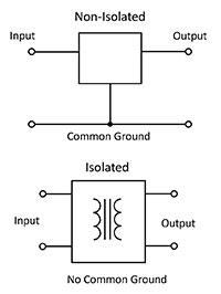
Non-isolated DC-DC converters
One could consider a series resistor to be a voltage converter or a non-isolated DC-DC converter, but it has little value as the voltage varies with load current. This can be improved by using a feedback-controlled transistor to maintain a constant voltage under all load conditions. In the simplest designs, the transistor is working in its linear area, so this type of device is known as a “linear” DC-DC converter.
With this approach, voltages can only be reduced and there is a lot of power dissipated in the transistor, which increases as the differential between input and output voltages increases. As such they have limited usefulness, and are only considered for specialist extreme low-noise applications.
A more flexible approach is to switch the transistor so that it is either fully on or off. In this “switched mode” configuration little power is dissipated in the transistor, and pulses of power are passed to the output where a capacitor acts as a smoothing reservoir. By increasing or decreasing the width of pulses, the output voltage can be increased or reduced, and this can be controlled with a feedback loop. This approach is far more efficient than with linear circuits, and is also able to increase or reduce the output voltage with respect to the input. Circuits that increase the voltage are often termed “boost” converters, while those that reduce voltage are known as “buck” converters.
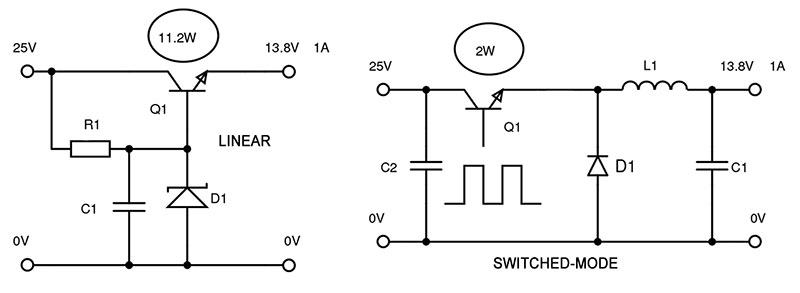
Figure 2:Linear and switched-mode loss comparison.
There are many different topologies of DC-DC converter that offer different features, performance and cost levels. On well-known approach is the SEPIC converter, which is able to produce a positive output that is higher or lower than a positive input. This type of converter is known as “buck-boost” and is valuable in situations where the input varies, but the output must remain constant – such as battery-powered applications.
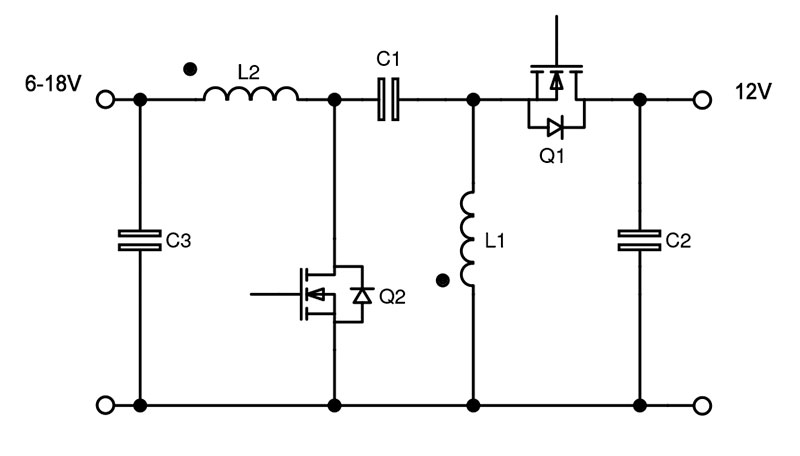
In common with many modern applications, DC-DC converter designers are constantly trying to improve efficiency while reducing the size of the solution. This is helped by increasing frequency as the size of magnetic components and capacitors can reduce. However, each time a transistor switches, power is dissipated, which reduces overall efficiency, meaning that there is a very important tradeoff to be made.
Modern technologies such as wide-bandgap semiconductors are changing the equation by promising lower losses at high switching speeds. Using materials such as silicon carbide (SiC) and gallium nitride (GaN), these leading-edge devices allow DC-DC converters to be constructed with output currents in excess of 100A and efficiencies above 95%. One such device is the PTH04040W from TI. This has a 60A rating and can deliver output voltages between 2.95 and 5.5V while occupying just 51.94 x 26.54mm of PCB area.
Modular boost converters are also available, such as the ABXS002A3X41-SRZ from GE Critical Power. This provides a 16 to 34V output at 2.3A from an 8 to 16V input in an area of just 27.9 x 11.4mm.
Sometimes non-isolated DC-DC converters are referred to as point-of-load (PoL) converters, as they are placed right next to the load (often a processor or FPGA) to reduce trace length and provide a number of benefits including a highly accurate voltage feed. Some PoLs are digitally controllable, meaning that the system itself can reconfigure its own power supply to suit load requirements. Processors, such as those from Intel or AMD, often use a special type of PoL honed for their specifications, known as a voltage regulator module (VRM).
Isolated DC-DC converters
There can be several reasons why isolation is incorporated into DC-DC converters. It can be used to prevent interaction between input and output grounds that can lead to ground loops. When cables link separate systems, such as with RS485 interfaces, an isolated converter will prevent potentially damaging currents moving between the two systems.
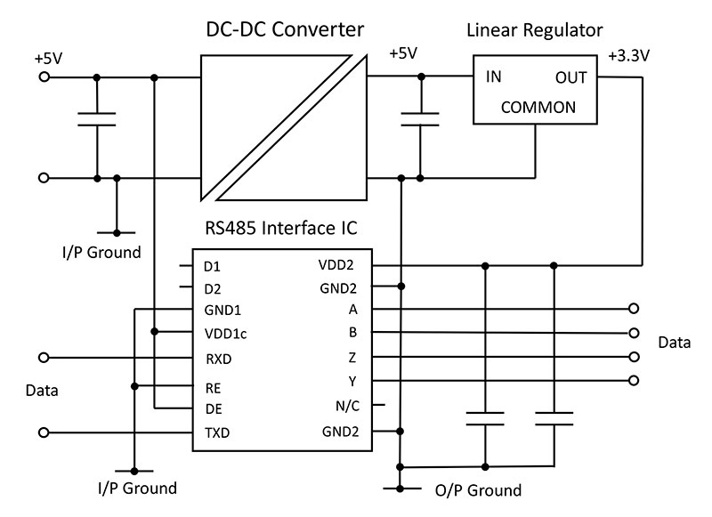
These so-called “floating” outputs can be connected to other DC rails or even ground. Connecting a positive voltage to ground produces a negative voltage that can be useful in analog circuits, to power operational amplifiers. Voltages can also be stacked to produce higher voltage rails.
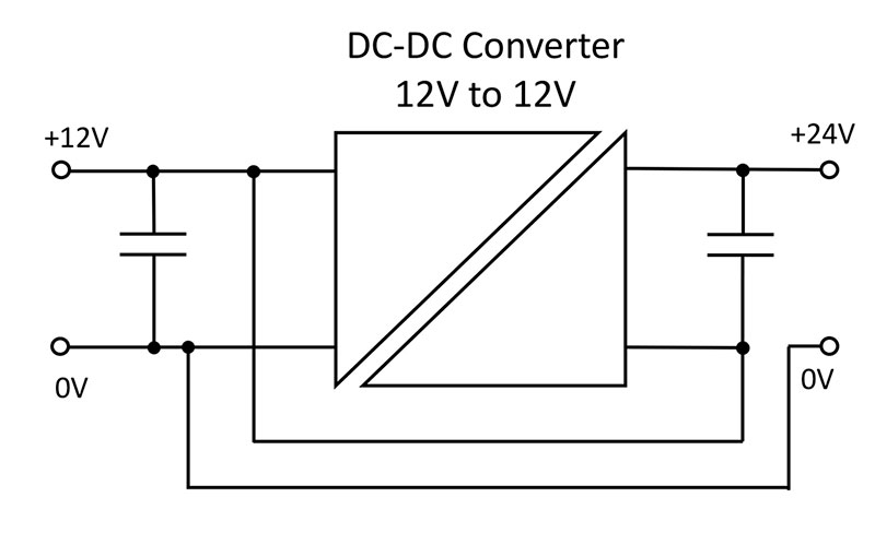
Isolated converters employ a transformer, which can also provide a degree of immunity to common-mode EMI and other noise.
Isolation is also a safety feature and is important even in DC-DC converters that only have low voltages present on the input and output. This isolation is a vital part of the system and contributes to the system rating. In a medical application the DC-DC must be rated for the highest system voltage, which is often mains at 230VAC. This is required so that no failure of any part of the system is able to connect the lethal mains voltage to the patient (or operator) under any circumstances.
In the latest version of the medical safety standards this type of isolation is known as means of patient protection (MOPP) and/or means of operator protection (MOOP), as offered by the THM 30WI series from Traco Power.
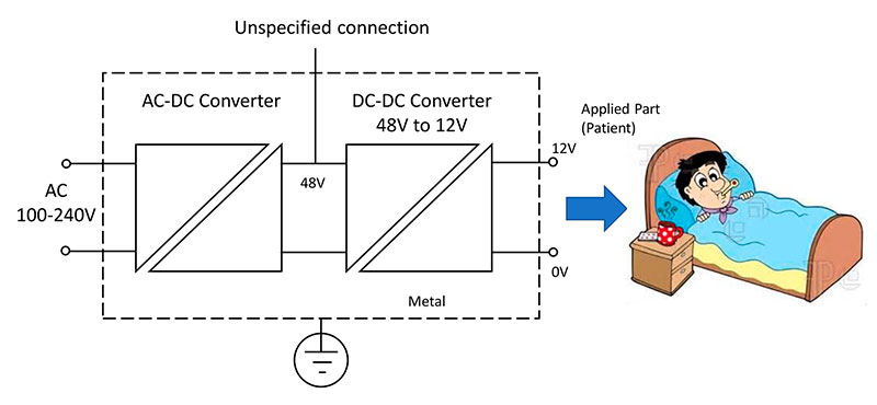
Isolation specifications can be confusing; sometimes the factory test voltage and duration are quoted (e.g. “3kVDC for 1 second”) but, unless reference is made to specific safety approvals, this cannot be relied on for safety isolation. Terms such as “basic” or “reinforced” are often used to describe safety agency-approved isolation schemes.
Some isolated converters have no particular regulation, as they are intended to be driven by a voltage that does not vary significantly. These “ratiometric” converters produce an output that is proportional to the input, usually 3:1, 4:1 or 5:1. They are relatively low cost, although they do require a minimum load to operate correctly. The semi-regulated output voltage is often regulated to the eventual voltage by a PoL.
As many systems are battery powered, or used globally with different line voltages, the ability to accept wide input voltage ranges is very useful. Many converters are able to accept a 2:1 ratio (e.g. 18 to 36V or 36 to 72V), although for challenging applications such as railways where voltages can be affected by dips and surges devices such as the CM1901-9RG from Bel Power are now available.
Understanding DC-DC specifications
When selecting a DC-DC converter it is good practice to consider the operating environment, particularly the operating temperature and the availability (or not) of any airflow to aid cooling. If insufficient cooling is available, the DC-DC converter may not be able to work to its full rated power, a process known as derating.
Efficiency is another critical parameter, especially in battery-driven applications. Care is needed here, as datasheets often quote the best possible figure, often at 75% or 100% load, although when operating at other power levels the actual efficiency achieved may be significantly lower.
Isolation should also be high on the list of considerations, including any particular safety agency requirements related to the application.
The noise produced by the converter will be an issue in many applications – this may interfere with external devices or sensitive analog circuitry within the system. A small and noisy converter may need large and expensive filtering, making it more expensive and larger than a better low-noise converter.
Once a converter series that meets these requirements has been found then the designer needs to select the correct voltage and give consideration to other features such as protection mechanisms and possibly the ability to be controlled digitally.


