Rudy Ramos, Mouser Electronics
Modern DC-DC converters come a huge variety of types and capacities. Towards the lower end of the power spectrum, designers often design discrete solutions themselves, but complexity rises as power increases so off-the-shelf modules become popular. However, new ‘micro module’ products are changing the point at which this makes sense.
Power is present in almost every electronic device and DC-DC conversion occurs everywhere – inside AC-DC power supplies to rectify the second stage or simply to create a voltage rail from another voltage. These days, many companies supply components, or even kits, to make low power DC-DC converters and support information is freely available – including reference designs and calculation tools. With all this support it is quite easy to design and build a ‘reasonably good’ low power solution and many engineers go this route, designing and qualifying their own simple designs.
As power increases so does complexity
With higher power levels, there are more areas to be concerned with. For example, an efficiency of just 75% produces relatively little loss with an output power of (say) 5W. Once the power level reaches 75W, then the losses at this efficiency level become significant and would cause the DC-DC converter to run very hot – or require significant cooling measures.
EMI also becomes a consideration as power increases and, as current rises especially when powering processors or digital circuits with ASICs or FPGAs, then dynamic load-step performance is a consideration – ensuring that under-shoot and over-shoot is minimized.
More powerful DC-DC converters usually power at least some critical areas of the system, meaning that control circuitry, monitoring and fault condition protection are almost essential. Safety agency approval is more often an issue with higher power DC-DC converters, adding to the complexity and extending development times – often significantly
While not all DC-DC converters are isolated, many are – and this will require an (often custom) magnetic component. Designing these and getting them to perform well is often regarded as a bit of a ‘black art’ – and then there’s all of the associated EMI issues to deal with.
Even when the design is done and debugged, there are downstream challenges including fitting the design onto the PCB without interfering with sensitive circuitry, sourcing custom magnetics – and more.
Make or Buy?
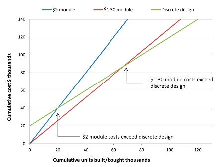
The ‘make or buy’ decision is not clear-cut and there is no specific volume point at which it switches from one to the other, many factors come into play. Production volume is a significant influencer as savings by ‘making’ are acieved many times over, but the extra time to market could mean that the opportunity is missed, or reduced. The few cents saved on the BOM cost may never make up for the sales lost in the extra months of development.
Risk is another significant factor. Designs do fail to perform, requiring at least one expensive respin of the board while a pre-certified module will almost always perform to expectations first time.
Payback calculations and risk analysis are useful tools, but it is almost impossible to quantify every aspect so, ultimately, the decision becomes a bit of a guess sometimes an educated one.
 Figure 1: Example payback analysis.
There are many reputable manufacturers offering ICs and other products for would-be designers of DC-DC converters and more products reach the market regularly. In order to attract customers and compete with their peers, these companies offer high levels of support and advanced tools to ‘get the job done’ – but the risk is still there – each application is different and EMI issues are common and often hard to solve, while designing for safety approvals will always remain a challenge.
While there are no hard-and-fast rules, discrete in-house designs were relatively common below 2A and modules were preferred above 10A, especially as using SIP devices made very efficient use of space. In the intervening space, between 2A and 10A the decision was not clear-cut. While discrete solutions presented challenges, the finished result was often more elegant that a bulky through-hole module.
µModules change the game
Linear Technology Corporation (LTC), now part of Analog Devices (ADI), has recently introduced their µModule® parts that provide another option in the mid-space between fully discrete and off-the-shelf module solutions. Described as a ‘Power System-in-a-Package’ these products include the all-important magnetic element of the design in a package that is simple to pick-and-place, just like any other SMT component. Now this solution is available, the threshold for make-it-yourself approaches to power is changing, and moving to higher current.
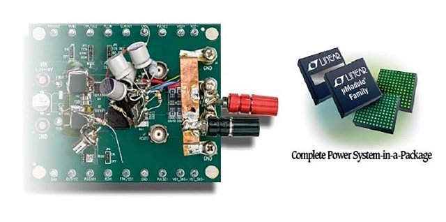
 Figure 2. μModule DC/DC regulators replace a complex PC board with active and passive discrete components and a single, simple, tiny, drop-in module. (Source: Linear Technology)
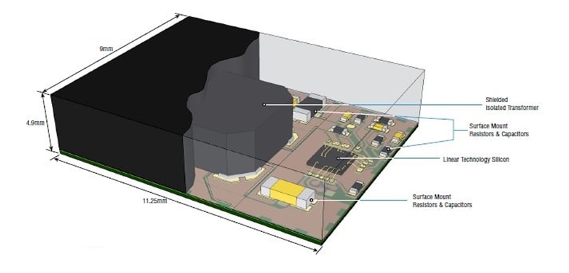
One of the reasons that µModules have a strong appeal is that they include technical features that simply could not be achieved with a discreet solution, no matter how sophisticated. The silicon is proprietary to LTC and the 6.25mm x 6.25mm x 1.82mm package neatly integrates this with a power MOSFET, passives and magnetics to allow for a 3A step-down regulator to be realized in a very compact space. Designers benefit from the ultra-low package that can be placed on the back-side of the PCB or even under some larger components such as heatsinks or processor devices.
 Figure 3. Typical µModule construction (Source: Linear Technology)
The extensive tange of modules incorporates a total fo 15 families which contain 100 different product variants, including step-up and step-down, inverting, battery chargers, LED drivers and digital power management. Isolated versions up to 725 VDC and agency-recognized 2kV AC are available.
μModule example – the LTM8045
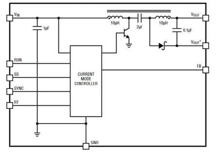
If we focus on a single part, the LTM8045 then we can look in more detail at the solution. This can be configured in multiple ways including as a (Single-Ended Primary Inductance Converter) where the positive polarity output voltage is lower or higher than the input voltage. An alternative configuration is as a ‘buck-boost’ converter with a negative output voltage that is higher or lower than the input voltage.
The input range is between 2.8 to 18.0V and the programmable output is in the range 2.5V to 15.0V. The current rating is up to 700mA at an output voltage of 2.5V. Operating frequency is in the range 200kHz to 2MHz and can be externally synchronized which is particularly useful in sensitive circuits, such as those incorporating an ADC.
Depending on how the solution is configured, efficiencies up to 80% are possible. The device provides for an extremely compact solution as it is housed in an 11.25 x 6.25 x 4.92mm BGA package and only requires a small capacitor on the input and output, as well as a couple of optional resistors to configure options. Additionally, functionality such as soft start, under-voltage lockout and enable are included in the module, saving valuable board space and reducing BOM cost.
 Figure 4. The LTM8045 μModule (Source: Linear Technology)
Key features of the range include:-
- Both non-isolated and isolated (agency rated) variants for applications requiring safety approvals and / or functional isolation
- Ultra-low noise, giving the ability to meet stringent EN55022 Class B EMI requirements
- Seamless buck-boost transitions, ideal for battery-powered applications where the input can vary above and below the output voltage
- Up to five outputs in a single μModule which can be individually controlled and paralleled for increased current
- Digital input / output (I/O) interface, with “read” and “write” settings from and to regulators via a serial bus, for close monitoring and control
- Remote sensing to adjust the output due to resistive drops in high current applications, especially where the power source is not close to the load
- Current sharing (or paralleling) of several μModule devices, including uniform distribution of current to the load to allow for higher power applications
- Inverting regulators that derive negative voltage outputs from positive voltage supplies
- Tunable compensation that alters the µModule loop response to achieve a specific output and transient response, thereby adjusting for complex loads and various output capacitor types
- Ultra-thin packages, so the device can be mounted on the back-side of densely-packed circuit boards
To ease the design task, for both experienced and relatively new designers, every μModule device has a dedicated demo board, user manual, layout guidelines and a full suite of documentation. Simulation models can be provided for all parts, along with complete designs in the industry-standard LTspice® format.
Conclusion
The μModule parts are changing the equation that determines whether a solution is best realized as discrete or module, fitting the mid-space between 2A and 10A. The extensive range includes 100 variants, each with a high level of specification and full qualification. The ability to tune, digitally control and monitor the final designs adds value, as does the defined performance small size and cost.


