
Thomas Brand, Analog Devices
QUESTION:
How could I measure the light intensity of different light sources?

ANSWER:
Use photodiodes which are sensitive to red, green, and blue light.
Determination of the light intensity can be crucial, for example, if you want to design the lighting of a room, or in preparing for a photo shoot. In the era of the Internet of Things (IoT), however, light intensity also plays an important role in so-called smart agriculture. Here, one key task is to monitor and control important plant parameters that contribute to maximizing plant growth and accelerating photosynthesis. Light is thereby one of the most important factors in smart agriculture. Most plants usually absorb light in the wavelengths of the red, orange, blue, and violet regions of the visible spectrum. As a rule, light in the wavelengths of the green and yellow regions of the spectrum is reflected and contributes only slightly to growth. By controlling parts of the spectrum and the intensity of light exposure throughout various life stages, growth can be maximized, and the yield ultimately increased.
A corresponding circuit design for measuring the light intensity over the visible spectrum, in which plants are photosynthetically active, is shown in Figure 1. Here, three differently colored photodiodes (green, red, and blue) are used, which respond to different wavelengths. The light intensity measured via the photodiodes can now be used to control the light source according to the requirements of the respective plants.
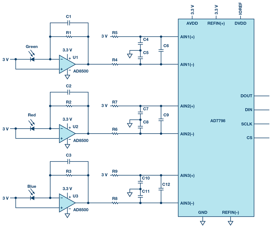
Figure 1. Circuit design for measurement of light intensity.
The circuit shown here is made up of three precise current-to-voltage converter stages (transimpedance amplifiers), one for each of the colors green, red, and blue. They are connected to the differential inputs of a Σ-Δ analog-to-digital converter (ADC), which, for example, provides the measured values as digital data to a microcontroller for further processing.
Conversion of Light Intensity into Current
Depending on the light intensity, more or less current flows through the photodiodes. The relationship between current and light intensity is approximately linear, which is illustrated in Figure 2. It shows the characteristic curves of the output current as a function of light intensity for a red (CLS15-22C/L213R/TR8), a green (CLS15-22C/L213G/TR8), and a blue photodiode (CLS15-22C/L213B/TR8).
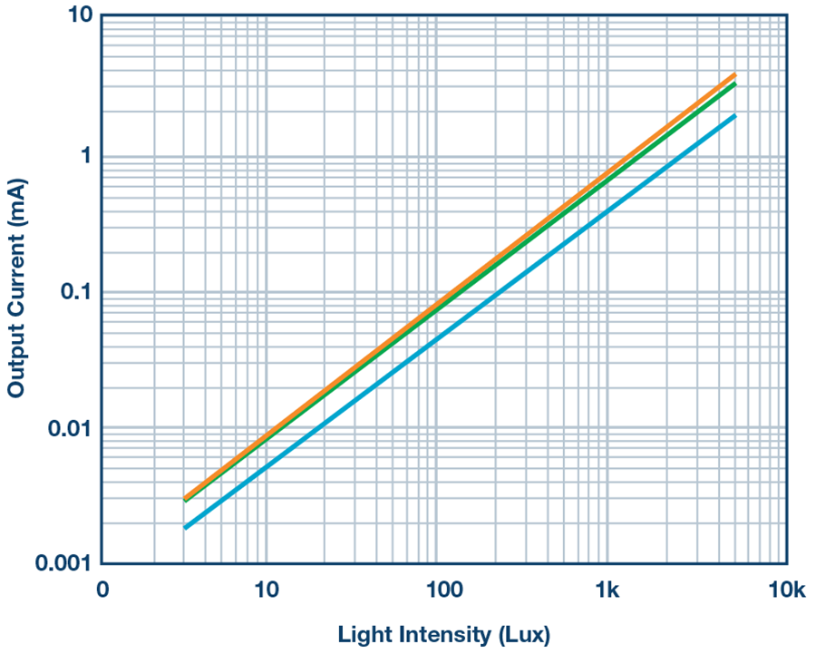
Figure 2. Characteristic curves of current to light intensity for red, green, and blue photodiodes.
However, the relative sensitivities of the red, green, and blue diodes are different, so the gain of each stage must be determined separately through the feedback resistance RFB. For this, the short-circuit current (ISC) of each diode has to be taken from the data sheet and subsequently the sensitivity, S (pA/lux), at the operating points determined from it. RFB is then calculated as follows:

VFS,P-P represents the desired full output voltage range (full-scale, peak-to-peak) and INTMAX the maximum light intensity, which is 120,000 lux for direct sunlight.
Current-to-Voltage Conversion
For a high quality current-to-voltage conversion, the minimal bias current of the operational amplifier is desirable because the output current of the photodiode is in the picoampere range and thus can cause considerable errors. A low offset voltage should also be present. With a bias current of typically 1 pA and a maximum offset voltage of 1 mV, the AD8500 from Analog Devices, Inc. (ADI) is a good choice for these applications.
Analog-to-Digital Conversion
For further processing of the measured values, the photodiode current that was first converted into a voltage has to be provided to the microcontroller as a digital value. For this purpose, ADCs with multiple differential inputs can be used, such as the 16-bit ADC AD7798. Thus, the output code for the measured voltage is as follows:

where
AIN = input voltage,
N = number of bits,
GAIN = gain factor of the internal amplifier,
VREF = external reference voltage.
For further noise reduction, a common-mode and a differential filter are used on each of the differential inputs of the ADC.
All of the depicted components are extremely power-saving, making the circuit ideal for battery-operated portable field applications.
Conclusion
Error sources such as bias currents and offset voltages of the components must be considered. Also, unfavorable converter stage amplification factors can impact the quality and thus the result of the circuit. With the circuit shown in Figure 1, light intensity can be converted into an electrical value for further data processing in a relatively simple way.
Author
Thomas Brand began his career at Analog Devices in Munich in 2015 as part of his master’s thesis. After graduating, he was part of a trainee program at Analog Devices. In 2017, he became a field applications engineer. Thomas supports large industrial customers in Central Europe and also specializes in the field of Industrial Ethernet. He studied electrical engineering at the University of Cooperative Education in Mosbach before completing his postgraduate studies in international sales with a master’s degree at the University of Applied Sciences in Constance.


