Reclosers are an integral part of our power grid, and with the help of modeling, a group of engineers discovered how to improve the development process for this crucial component
 It’s a very stormy day with high winds. A tree branch falls to the ground, and on its way down it touches two overhead cables and causes a momentary short circuit. At home, though, you merely notice the lights flicker for a second. The fact that power isn’t cut off for longer is thanks to a device called a recloser. It combines a circuit breaker that trips if an overcurrent is detected with reclosing control circuitry that automatically restores power to the affected line if the fault clears itself quickly, which happens around 80 percent of the time.
In such situations, a recloser has to withstand harsh environmental conditions and heavy contamination and might be put into service only once or twice a year. But with the increasing use of renewable energy, where sources of power from wind or solar energy are constantly being brought onto or removed from the grid, reclosers are needed to configure the smart power grid accordingly and protect it from the possible adverse effects of adding temporary sources of power.
Manufacturers such as ABB are working to develop reclosers that are more reliable. For example, ABB’s Grid Shield recloser is rated for 10 000 full-load operations. With the help of COMSOL Multiphysics, ABB engineers have been able to improve their performance.
Magnet Optimization is Key
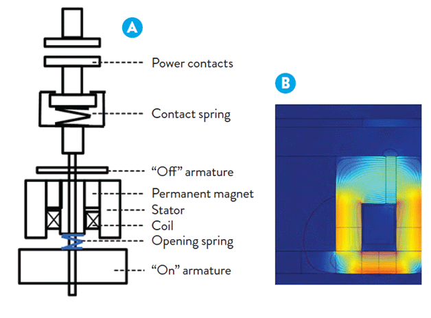
The main device for opening and closing this type of recloser, shown in Figure 1(a), is a single-coil actuator. The current flowing through the coil is sup- plied by a power amplifier control circuit. Depending on its direction, the coil current creates a magnetic field that overcomes the force of the permanent magnet and draws the “On” Armature to the stator to close the circuit or draws the “Off” Armature to open the circuit; the open position is reached when the repelling opening spring is discharged.
A key element of the recloser is the permanent magnet. Our goal was to optimize the magnet’s size while ensuring excellent switching properties. In doing so, design engineers must examine the mag- net’s size and find the optimal material and stator properties and the corresponding settings for the electronic control unit.
Simulation Work Flow
An overview of the simulation work flow is as follows—first, we create a 2D simulation to get a rough estimate of how to tune the system and size the mag- net. At this point we also create the power amplifier circuit to drive the Coil to couple it to the 2D magnetic simulation. We then feed results from COMSOL into an optimization program to help us select the best mag- net size. Once we have selected a magnet configuration, we then work with a 3D model to see the full current distribution and perform validation.

Capturing the Concept in 2D
The 2D model computes the holding force in the “On” and “Off” positions so as to identify the optimal actuator dimensions and properties of the permanent magnet for different materials and ambient temperatures. We start by calculating the magnetic flux density using the magnetic fields physics from the AC/DC Module. We then use the electrical circuit feature to couple the actual power amplifier schematic (see Figure 2) and component values to the magnetic simulation. The voltage (Va) across the output coil on the right is then easily passed on to the AC/DC Module.
We examine intermediate results in a plot such as Figure 1(b), which shows the magnetic flux throughout the actuator. The geometric parameters as well as the material proprieties are adjusted with respect to the design constraints until an optimal magnetic flux density is achieved. Based on a given material, to help find the optimum cross section of the magnet and the drive current we perform optimization of the 2D static model.
The coupling between the optimization software modeFRONTIER and COMSOL Multiphysics is realized via LiveLink™ for MATLAB®. At first, modeFRONTIER initiates MATLAB®. The initial parameters (e.g., the actuator geometry, permanent magnet type, and coil excitation) are set via LiveLink™ for MATLAB®, which starts COMSOL Multiphysics. Once the 2D static calculation is finalized, the postprocessing of results begins. Afterwards, the next iteration is ready to start. Depending on the actuator type and associated postprocessing, the process just described lasts approximately 100 seconds.
The optimization takes into account the geometry for the actuator with respect to size, weight, and holding force. Once we have selected a certain magnet configuration, we feed this information back into COMSOL Multiphysics using LiveLink™ for MATLAB®.
Verify the Design in 3D
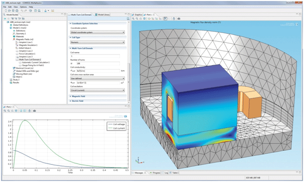
Once a 2D steady-state configuration is selected, a dynamic 3D model is run to see the effects as the armature moves relative to the coil and stator. The ability of COMSOL Multiphysics to solve global ordinary differential equations (ODEs) is used to compute the force on the armature and then its acceleration and position. There is a constantly changing air domain between the actuator and the “On” Armature, and it is necessary to deform the mesh to reflect this movement. The global ODEs solution is driving this movement, while the mesh deformation is automatically handled by the moving mesh technology available in COMSOL Multiphysics. These results are used to recalculate the force, find the new position, and rebuild the mesh until the system reaches final equilibrium with the given driving current.One output of this dynamic simulation is the transient magnet flux density, as shown in Figure 3.
One particular feature we found very useful was the multiturn coil domain. In general, it is very challenging to come up with an accurate 3D coil model. Without a tool such as this, it would be necessary to model each turn in a coil. In this case the coil has 400 turns, and the resulting mesh would be extremely challenging to handle. COMSOL did a very nice job in easing this process, whereas with other software we would simply have to make assumptions about how many turns to model.
Greatly Reduced Development Time
Both the 2D and the 3D simulations are being validated against measurements on prototypes. For the 2D model, the validation consists of comparing the holding force with the one obtained by means of simulation. With respect to the 3D dynamic model, the validation is realized both on the electrical side (coil current and voltage) and on the mechanical side (travel curve).
With the validated simulation, we can now experiment with the design and find new, improved configurations. This will be important to help us reduce development time. Since we can calculate a 2D model in just a few seconds, when we find a design worth pursuing, we can then run the 3D simulation right away.


