A new reference design called Sonoma from Maxim Integrated that meets the high-accuracy and low-cost needs of energy-measurement applications. This subsystem performs accurate AC energy measurement while utilizing a unique, low-cost galvanic isolation architecture
Measuring electrical power consumption—dynamic current and voltage—is a fundamental requirement of many high-precision applications like electric vehicle charging stations, industrial control and automation systems, data centers, smart home appliances, solar inverters, street lighting, distribution automation, smart electricity meters, and any future smart grid application. We cannot, in fact, emphasize enough the importance of precision energy measurement for these applications. For example, flawed energy measurement—inaccurate or even untimely—for an electrical utility severely hampers the utility’s ability to successfully manage customer time of use and optimize energy delivery.
There is now a reference design called Sonoma that meets the high-accuracy and low-cost needs of energy-measurement applications. This subsystem performs accurate AC energy measurement while utilizing a unique, low-cost galvanic isolation architecture. Sonoma uses a shunt resistor to accurately sense current and voltage without a transformer. This architecture eliminates bulky transformers and a power supply, sending both data and power through the same pulse transformer. In this article we examine the hardware and development kit firmware of the new Sonoma reference design. Lab tests verify performance. We will explain why the Sonoma is so valuable for energy measurement in smart grid applications.
Leveraging Low-Cost Galvanic Isolation and Small, Integrated Sensing Resistors
Traditional AC measurement applications use bulky and expensive voltage/current transformers for sensors to step down voltage to a range which a solid state analog-to-digital converter (ADC) can measure accurately. While extremely functional, especially in high-voltage applications, current and voltage transformers are expensive and bulky. There are also hidden costs and design challenges that are unwelcome to engineers trying to reduce size and costs. (See the Sidebar discussion of these design trade-offs.) Alternative architectures place isolation between the measurement subsystem and the system microcontroller. These architectures require isolation of both data and power, thereby increasing the number of system components. The Sonoma (MAXREFDES14#) energy-measurement subsystem provides galvanic isolation from the system with a single pulse transformer and uses resistors as the sensing elements. The result is a small, cost-optimized board (Figure 1).
Implementing the Energy-Measurement System
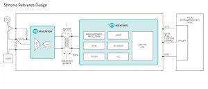
The Sonoma design utilizes an isolated energy-measurement processor, a multichannel, precision ADC, a pulse transformer, an optional 20MHz crystal oscillator, and the appropriate sense resistors for converting AC voltage and current into measurable signals (Figure 2). With the embedded load-monitoring-unit (LMU) firmware and nonvolatile (NV) storage of calibration and configuration data, Sonoma is a complete energy-measurement subsystem ready for integration into any design.
Figure 2.The Sonoma subsystem uses the MAX78615+LMU energy-measurement processor; a MAX78700 isolated, multichannel ADC; and resistive sensors for measuring 2-wire AC loads up to 8A.
Hardware Description
Sonoma connects to Pmod-compatible FPGA/microcontroller development boards. The flexibility of the Pmod specification is important because it allows for both 3.3V and 5V modules and various pin assignments. Sonoma requires a supply voltage of 3.3V from the Pmod connector and uses the SPI pin assignments.
At the heart of Sonoma is the MAX78615+LMU energy-measurement processor. Positioned in the isolated domain of the system, it simplifies integration into the existing low-voltage domains found in many embedded systems. Pages of the device’s internal Flash memory are reserved for storing configuration and calibration data.
Across the isolation barrier, the MAX78700 ADC connects to the MAX78615+LMU processor through a single, low-cost pulse transformer. Using unique remote sensor technology, the ADC receives timing and configuration data, and power from the processor. The ADC responds with converted data samples of the voltage, current, and die temperature.
The board is configured for a SPI interface between the processor and host system (Figure 2). The design files provided with Sonoma support this mode. As an option, you can remove R10 which will place the device in UART mode.1
The MAX78615+LMU processor contains a fixed set of preprogrammed scaling factors2 (optimized for a given bill of materials, BOM) in the NV memory to perform proper voltage, current, and power calculations. The resulting measurement accuracy is directly related to the initial tolerance of the passive components found in the sense circuit. The Sonoma reference design utilizes fixed-gain coefficients and offsets derived from examining 10 initial units.3
LX9/ZedBoard™ Firmware Description
The Sonoma design was verified using the LX9 and ZedBoardplatforms. Project files, device drivers, and example code are currently available. The firmware provides an immediate interface to the MAX78615+LMU processor for register read and write commands. The firmware is in C and custom Sonoma-specific design functions are available. The complete source code is provided to speed customer development. Additionally, the Sonoma design can easily be used by any microcontroller or FPGA development board because of the simplicity of the onboard Pmod-compatible connector. The complete source code and documentation are provided at http://www.maximintegrated.com/sonoma.
Lab Measurements
Lab tests were performed and duplication of this test data requires an AC source with high accuracy.
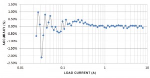
Figure 3 shows the measured power accuracy of a random Sonoma board over load current. The error is less than ±3% with a fixed set of gain/offset coefficients for the sensors. Calibration of the sensors would achieve higher accuracy. Lower current levels produce higher errors because the measurable signal is closer to the noise level. Averaging multiple data reads or increasing the accumulation interval of the MAX78615+LMU will reduce the relative error.
Figure 3. Detailed active power load line; power accuracy: 23.5mA to 7.9A at 120VRMS/60Hz and at room temperature.
Sonoma and the Smart Grid
Now let’s look at smart grid applications for a moment. Energy measurement provides critical data in all locations of the electrical grid, including transmission, distribution, and consumption. Sonoma is most effective in submetering and endpoint consumption applications. For example, an electrical vehicle charging station can use Sonoma to measure the power consumption and then provide that information to the utility and the consumer for better energy usage management. The power used for charging electrical vehicles is often billed at a different rate, making it a submetering application and requiring energy measurement to calculate the specific costs for charging.
In the smart grid, demand response (DR) enables individual customers to contribute load reduction during the peak load times. There are two primary ways to reduce peak load. First, high-energy consumption devices, such as air conditioners and pool pumps, are connected to a smart grid network with energy measurement and some form of communication added to them. Then, consumers can allow their respective utility to reduce load by actually controlling those appliances during the peak load time.4 Second, utilities can implement time-of-use pricing, meaning that they provide time-varying pricing to consumers. Consumers then manage their use of specific appliances to reduce cost. All of these “smart” appliances need a device like Sonoma to learn the energy consumption of each appliance so the utility can calculate the associated energy cost.
The Sonoma reference design will be especially beneficial because of its smaller size. With data and power isolation achieved using a single pulse transformer, the traditional bulky transformers and an isolated power supply are no longer needed. The high integration reduces the size and cost of Sonoma, relative to other accurate energy-measurement solutions. The preloaded and upgradeable firmware is adaptable to existing setups and greatly simplifies design time.
To many consumers the smart grid means a smart meter connected to their residence. However, the smart grid consists of many more applications than just smart meters. Some of these applications are yet to be discovered and will provide tremendous benefits in the reduction and optimization of energy consumption. In all cases, energy measurement must be part of the system. Reductions in size and system cost, as implemented in Sonoma, will further drive adoption of accurate energy measurement into the smart grid of today and tomorrow.
Sidebar: Challenges for Designing with Voltage/Current Transformers
If isolating at the sensors, one must use two transformers (current and voltage) which are bulky. The AC wiring in and around these transformers consumes space as well. The benefit here is that there are no isolated power requirements nor need for optoisolation of the data lines.
If a design is only using a current transformer or a shunt, then one may need a nonisolated power supply. This often adds a power domain to the design plans. There are multiple ways to accomplish this, but it always involves a capacitor and/or transformer that require more space. For data isolation, the optoisolators use considerable space because of the larger lead-pitch package options needed for AC voltage levels. Knowing how many traces to isolate and at what speed makes the costs highly variable as well. For example, someone may plan to isolate two lines (RX/TX), but later need a digital IO isolated as well for an alarm function. Finally, the nonisolated power must scale with the optoisolation as well. (Isolating high-speed SPI, for example, consumes a decent amount of current which may increase the cost/size of the nonisolated power supply.)
Using Sonoma, everything is bounded. Size and costs are known at the outset and there are no special power-supply requirements nor need for optoisolation of the data lines.
Endnotes
- For more information about the conversion to UART mode, please see the MAX78615+LMU data sheet on host interface options and protocols, http://www.maximintegrated.com/MAX78615.
- For more information, refer to the scaling registers section in the MAX78615+LMU data sheet.
- An example of Southern California Edison’s Automated Demand Response program, https://www.sce.com/wps/wcm/connect/719e7ab6-2e6b-4f0a-aeb6-54736ec9874f/24147_AutoDR_Customized_2_v10.pdf?MOD=AJPERES
Pmod is the trademark of Digilent Inc.
ZedBoard is a trademark of ZedBoard.org.
About the Author
Gordon Lee is a Senior Member of Technical Staff at Maxim Integrated Products since June 2005. His primary focus has been on various types of sensors, signal processing, high-speed ADC application, and as well as FPGA HDL and embedded software design. He holds an M.S. in Electronics Engineering from San Jose State University.


