
By Carlos Castro, James Colby and Stefan Edenharter, Littelfuse
Although Hybrid and Electric Vehicles are significantly more energy-efficient than conventional combustion engines cars, the significant increase of electronic systems requires new and additional concepts for circuit protection. Specific technologies are necessary for high reliability applications like battery management or under harsh environmental conditions of a transmission integrated inverter.
Legislation translates the needs for environmental protection into stronger regulations for improved fuel efficiency. The European Union limits CO2 level to 95g/km in 2021 and in other regions are following very similar regulations. The only way for all car manufactures to fulfill such regulations is the introduction of hybrid and electric vehicle in their portfolio. This is increasing even more the amount of electronics and specifically high voltage/current applications (inverter, DC-DC converter, charger…). Therefore, the needs for specific circuit protection solutions for those requirements are increasing.
Due to the electronic nature of these new systems, it is very important that protection is considered early in the design phase to ensure the most effective treatment. Unfortunately, during the design phase of the systems, circuit protection is sometimes underestimated or even ignored. But why is circuit protection so important? It´s important not only because it helps electronics to maintain its design functionality, but also to enhance reliability; an important aspect of occupant safety, which in many cases feeds into the most important aspect of protecting life.
Battery Management System
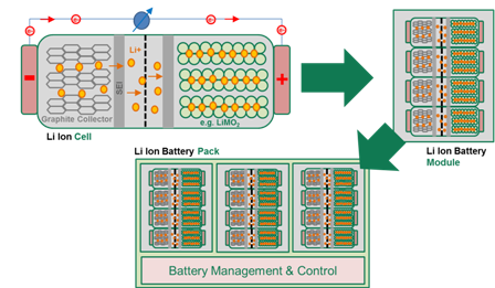
Electric and hybrid vehicles require a portable energy storage to power the electrical powertrain component. The key is to make this conversion as efficiently as possible in a compact package (i.e., converters with high power density and energy density) with minimal environmental pollution.
The desirable features of batteries for EV/HEV applications are
- High power/energy density to reduce space and weight.
- High charging current to reduce charging time
- Long calendar and cycle life.
- Good cell balancing and pack management circuits to increase efficiency and mileage
- Reasonable cost
Batteries in EV/HEV are used are made as a pack, which is the series and parallel combination of several battery modules. The series parallel combination is configured based on the DC-link voltage required and the energy capacity of the battery. Pack management circuit ensures reliability and protection against overcharge, over discharge, short circuits and thermal overloads. The battery health condition and faults are also reported by the pack management circuit.
Furthermore, protection of the Battery Management System itself is required to keep this important system reliable and safe under all conditions (assembly, maintenance and normal operation).
Figure 2 shows a high voltage battery system including the main blocks.
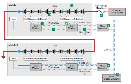
The main protection needs are:
- Sense Line Fuse to protect from shorting of sense lines: depending on the battery system, up to 200 sense lines are installed to measure the voltage of each cell to determining their state of charge and state of health. Shorting can theoretically happen between random sense lines depending on failure modes. Potential Failures: car accident or assembly issues which results in leakage of coolants or other liquids that can build conductive deposits.
- Cell Monitor IC Sense Line Input Overvoltage Protection: protects low voltage (5V) input terminals of Cell monitor from transients. Hot Plug Transients occur during assembly and maintenance of battery pack; other transients can be induced from vehicle systems like charger, inverters, and motor drives either via conduction or inductive coupling via adjacent cabling
- Overvoltage / ESD Protection for Daisy Chain I/F (e.g. Hot Plug, ESD). The circuit protection device should have a low capacitance (preserves signal integrity and minimizes data loss) low clamp voltage, small form factor and a power capability from 10 to several 100W.
- High Voltage TVS across Battery String for Transient Protection (e.g. Hot Plug)
-
-
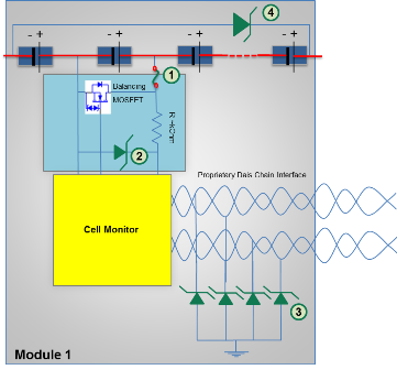
Figure 3: Sense line and cell monitor protection Overvoltage / ESD Protection for CAN Bus I/F: CAN Bus is the typical interface in order to link the Cell Monitoring Controllers to Higher Level BMS Controllers which then communicate with other controllers in the car. In the densely packed environment of a car battery system CAN lines can be subjected to overvoltage stress caused by ESD (e.g. during assembly & maintenance) or other transients introduced from other car systems via coupling or via conduction.
High Voltage / High Current fuse for power line protection: The high voltage / high current main fuse is the last resort of safety in the case of excessive current or short circuit events in the high power system of the car. Suitable fuses need to be well coordinated with other fuses being downstream in the system (e.g. junction boxes). Fuse needs to be able to withstand several thousand amps and need to be able to continuously conduct high amount of energy for a long time.
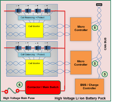
Figure 4: Microcontroller and power line protection On-board Charger
The block diagram of a typical on-board battery charger used in electric and plug-in hybrid vehicles is shown in in in Figure 5
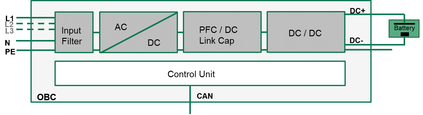
Figure 5: Battery charger circuit topology The circuit consists of a bridge rectifier at the input followed by a power factor correction (PFC) circuit, and then a full-bridge DC/DC converter.
The main protection needs are:
AC Input Line(s) Fuses: Requires Automotive Grade Fuses for Over Current Protection that can conduct high currents (i.e. 32A) at voltages up to 250 VAC single phase; high interrupt rating and ability to withstand vibrations, surge transients and thermal cycles are key.
-
-
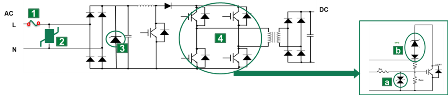
Figure 6: Bridge rectifier, power factor correction (PFC) and full-bridge DC/DC converter and protection devices AC Input Line(s) Transient Protection: Due to the direct connection to the power grid transient (8/20µs) protection with MOVs is required; the MOVs used need to work at elevated temperatures (125°C) and need to offer AC line working voltages. AEC-Q200 approval is a must have.
-
- DC Link Capacitor Protection: Even though DC Link Capacitors are intended to filter certain transients they still might need protection in certain cases; fast acting Auto Grade TVS Diodes can protect these costly parts
-
- Gate Overvoltage Protection: in former times Zener Diodes were used but these do not provide the same advantages as TVS Diodes like fast response, higher surge capability and better reliability.
Active Clamping protection: Direct feedback of the collector potential to the gate. If the collector-emitter voltage exceeds the breakdown voltage of the clamping element, a current flows to the gate. As a consequence the gate potential raises and so reducing the collector current slope resulting in a stable condition. The voltage across the IGBT is then determined by the design of the clamping element.
-
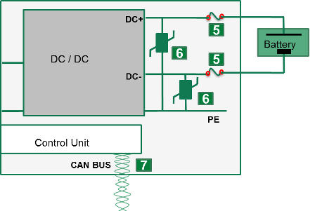 High Voltage DC Link Over Current Protection: Helps to clear dangerous short circuit conditions that can be caused due to faults in the OBC or Battery Pack or by external events like a car accident.
- High Voltage DC Link Over Voltage Protection: Clears overvoltage transients that can be introduced by switching actions (hot plug) or that are introduced by other systems of the car
- CAN Bus – ESD and Transient Protection: the OBC communicates via CAN Bus with other systems like the BMS. In the densely packed environment of a car CAN lines can be subjected to overvoltage stress caused by ESD (e.g. during assembly & maintenance) or other transients introduced from other car systems via induced or conducting coupling.
ISO 10605 and ElectroStatic Discharge (ESD) Protection
This international standard is specific to road vehicles and specifies various ESD test methods for evaluating electronic modules. These modules include everything from Infotainment and Connectivity solutions to GPS Receivers to Control Modules for Battery and Charging Systems. The common denominator in each of these examples is the need to be connected as they will be in communication with, and controlled by, the system processors. Typically, the control bus is CAN or LIN bus, but the market is beginning to explore faster buses including Ethernet and the more automotive-specific, BroadR Reach. With respect to reliability concerns, the data buses provide the needed communication path, but also can be the entry way for electrical transients like ESD.
AEC-Q101 – Component Level Standard for Quality
While ISO 10605 focuses on electrical hazards, AEC-Q101 is an environmental specification. For components to be considered AEC-Q101-compliant, they must be able to withstand the harsh automotive environment characterized by thermal shock and temperature cycling, high humidity and extreme temperatures. Thus, it ensures that when the component is installed in the automobile, it will not fail due to any inherent weakness.
AEC-Q200 – Component Level Standard for Quality
In the same away that Semiconductor devices need to meet minimum requirements for quality in automotive application, Passive devices also need to meet similar quality standards. In this case, the ESD solutions include Multilayer Varistors and Polymer-based ESD devices. Usage if these technologies are with MLVs for lower-speed circuits like CAN and LIN, and Polymer ESD devices for higher-speed circuits like Ethernet and BroadR Reach.
Drive Train Circuits Requiring Protection
Every circuit in an automobile is sensitive to damage from electrical transients. No matter where the component or circuit is located, it will be subjected to harsh conditions and temperatures within the vehicle. The following list describes some of the most popular automotive circuits requiring protection:
- Legacy communication buses—controller area network (CAN) and local interconnect network (LIN): These are the most popular communication bus standards, which cover 50 to 75 percent of the circuits within a car. They have been used for many years, and remain popular due to their reliability and fault tolerance.
- The CAN bus allows microcontrollers and devices to communicate within a vehicle, without the use of a host computer. It is a message-based protocol specifically designed for automotive applications. CAN systems handle everything from power steering to the critical drive-train communications between the engine computer and the transmission.
- The LIN bus is a serial network protocol used for communication between components in vehicles and offers a cost effective serial network. It is typically used to handle simple electromechanical functions such as moving the power seats and toggling the cruise control.
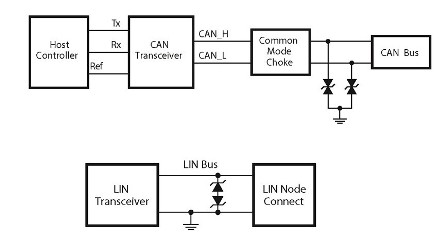
- Due to their near-ubiquitous presence in the automobile, these buses will have exposure to ESD during module installation and during the operation and servicing of the vehicles. So, they will have a high chance of transient exposure—which could cause a failure of the CAN or LIN transceivers.
These figures show the typical ESD protection of CAN and LIN buses. Since CAN bus is a two-channel circuit, the most common solution is a two-channel Diode Array. The LIN bus is only one-channel, so the ESD solution is a discrete ESD Diode or Multilayer Varistor.
 High-speed digital buses—Ethernet, BroadR Reach ports: Ethernet has historically been used in Telecommunication systems providing a connection between Routers, Switches and Access hardware. It is a very reliable solution with a proven track record. In recent years, there has been a push to improve the speeds that are provided by existing buses like CAN and LIN. Ethernet is initially being used in the 100Mbps version; this provides a significant boost to the capabilities of CAN bus, which are currently maxed out around 1Mbps. Likewise, the automotive-specific BroadR Reach is targeted at 100Mbps throughput and may be chosen for its simpler two-wire configuration. Ethernet requires the use of four wires.
- The need for more bandwidth is driven by the addition of many more controller modules and the desire to simplify the communication network in the vehicle (which can also reduce the amount of cables, and therefore the overall weight). Regardless of which communication solution is chosen, there are two and four-channel low-capacitance ESD Arrays available to provide the needed protection.
Until an Industry Standard is developed, it is important to work with the fuse supplier to verify that they endorse the fuse solution. This will ensure that both the supplier and system designer are aligned in their selection of fusing solutions that are appropriate for the harsh automotive environment. Ultimately, it is in the system designers’ best interest to make sure that the fuse is selected such that it performs its intended task and does not fail due to the conditions of the application.


