29/03/2024
Anritsu Corporation introduces its newly developed Butler Matrix 4×4 (0.6 GHz to 7.125 GHz) MA8114A to expand Butler Matrix[*1] module lineup of simulating MIMO connections.
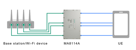
The MA8114A is a Butler Matrix transmission path with 4 input and 4 output ports and supports the 6 GHz band (5.925 GHz to 7.125 GHz), which is not supported by the existing Azimuth STACSIM-WB-(Static Channel Simulator) (ACC-339) used for evaluating 4×4 MIMO throughput of LTE/5G base stations and Wi-Fi devices.
Development Background
LTE/5G Base station and Wi-Fi device vendors use the OTA[*2] test environment to evaluate the maximum throughput with 4×4 MIMO for their products. This approach has the problem of low reproducibility of measurement results, however, because the transmission environment varies depending on the distance to the User Equipment (UE). While improving the reproducibility requires connecting the two devices using an RF cable, a simple coupler cannot simulate the MIMO transmission environment. The MA8114A ensures highly reproducible measurements.
The upper-limit frequency for NR FR1 has been extended beginning with 3GPP Release 17, and the 6 GHz band has been added to Wi-Fi 6E/7. The MA8114A supports a frequency range up to 7.125 GHz in preparation for countries launching services on new frequency bands.
Anritsu helps customers build a stable 5G/Wi-Fi evaluation environment and efficiently test throughput.
The product lineup of the Butler Matrix module also includes the Butler Matrix 8×8 (0.6 GHz to 7.125 GHz) MA8118A with 8 input and 8 output ports, which supports a frequency range up to 7.125 GHz as well. The MA8118A can be used not only for 8×8 MIMO throughput evaluation but also to enable efficient testing of devices having multiple RF ports.
Learn more about the Butler Matrix Module
Technical Terms
[*1]: Butler Matrix
A type of microwave beamforming phased array proposed in 1958 by Judith Butler et al. with multiple input and output ports to divide power input to one port equally to output ports at different phases.
[*2]: OTA
Abbreviation for Over The Air. As the Tx/Rx radio performance of a wireless device is measured over the air, the use of an OTA chamber, which is an anechoic chamber designed to block external radio waves, is recommended.


