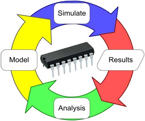
A typical IC circuit simulation uses mathematical models to replicate the behavior of the circuit. Simulation software allows for modeling of circuit operation and is an invaluable analysis tool. Its high accuracy and modeling capability, have make simulation a very essential tool in Analog & RF IC design. IC simulation software engages the user by integrating them into the learning experience and helps to analyze, synthesize, organize, and evaluate content and result of the ICs. In this article ahead, we shall be talking about some of the professional Analog & RF IC simulation software tools available in the market.
Simulating an IC behavior before actually building it can greatly improve design efficiency by diagnosing faulty designs and providing insight into the behavior of IC. For integrated circuits, the tooling or photo-masks is expensive, breadboards are impractical, and probing the behavior of internal signals is extremely difficult. Therefore almost all IC design relies heavily on simulation. A common tool for the electronic circuit designer is circuit simulation software. Although most often called simply a simulator, it is a software application that typically may include many functions beyond electrical circuit simulation, including schematic capture, printed circuit board layout, and bill of materials generation.
Most circuit simulator software grew out of a public domain program called SPICE (Simulation Program with Integrated Circuit Emphasis) developed at UC Berkeley in the 1970s. The original SPICE program operated in a batch mode and was text based. That is, the user created a text file which described the circuit using a special circuit netlist syntax. This file also included simulation directives which told the software what type of simulation is to be performed. The SPICE program read the input file, performed the appropriate analyses, and produced a text output file that contained the results. Graphs of output functions were drawn using text characters in a low resolution fashion. It may not have been very user friendly, but it was functional.
Over time EDA companies began adding graphical “back-ends” that could produce better looking graphs and plots of the simulation results. A next obvious step was to add a graphical interface for building the circuit (GUI). This had the dual benefit of both describing the circuit for the simulation engine (generating the SPICE netlist) and allowing for the production of publication quality schematic diagrams. Some of the early popular graphical versions included PSpice and Electronics Workbench. Eventually, functionality to create printed circuit board layouts from the schematics was added, along with supporting features such as electrical and design rule checking and Bill of Materials.
Simulating an IC is not always a similar job. Some simulators integrate a schematic editor, a simulation engine, and on-screen waveforms and make “what-if” scenarios easy and instant. They also typically contain extensive model and device libraries. These models typically include IC specific transistor models such as BSIM, generic components such as resistors, capacitors, inductors and transformers, user defined models (such as controlled current and voltage sources, or models in Verilog-A or VHDL-AMS). Printed circuit board (PCB) design requires specific models as well, such as transmission lines for the traces and IBIS models for driving and receiving electronics. Also there are analog IC simulators, popular simulators often include both analog and digital simulation capabilities, and are known as mixed-mode simulators. Another one getting popular now days are RF simulators.
More recent features include instrumentation simulation. That is, simulations of real world commercial measurement devices may be used as part of the circuit simulation. In this way, a sort of “virtual lab bench” may be created. Some packages, such as Fritzing, also include physical imagery of devices and proto-boards. With this feature, the circuit being designed will look very similar to the actual circuit sitting on your lab bench. That is, if a transistor is used in the simulation, it will look like a real transistor instead of the standard schematic symbol. While this may initially appear to be very useful, especially for beginners, in practical terms it sometimes slows down the design process by making the schematic less clear and more cluttered to the user.
Industry Trends – Analog & RF IC Simulation
Industry is seeing changing trends in analog & RF IC simulation, in both physics (the need to bring in physical effects early in the design process) & statistics expertise. The emerging electronics trends see a pull from customers & designers for simulators that are faster and better. Simulators are getting faster both in simulation time and by easier-to-use multi-core and multi-machine implementations. Simulators are also getting better. They converge on a broader range of circuits, handle larger circuits, and more cleanly support mixed-signal circuits. There’s another trend: meta-simulation. This term describes tools that feel like using simulators from the perspective of the designer. Just like simulators, meta-simulators input netlists, and output scalar or vector measures. However, meta-simulators actually call circuit simulators in the loop. Meta-simulators are used for fast PVT analysis, fast high-sigma statistical analysis, intelligent Monte Carlo analysis and sensitivity analysis. They bring the value of simulation to a “meta” (higher) level. Statistical analysis, design-of-experiments, and corner modes are some of the terms imply the need to address variation and a good EDA tools handle variation, while allowing the engineer to efficiently focus on designing with familiar flows like corner-based design and familiar analyses like PVT and Monte Carlo. Temperature variation can also be modeled to simulate the circuit’s performance through temperature ranges.
Some of the Simulators available
Simulink from Matlab
 Simulink® is a block diagram environment for multi – domain simulation and Model-Based Design. It supports simulation, automatic code generation, and continuous test and verification of embedded systems. Simulink provides a graphical editor, customizable block libraries, and solvers for modeling and simulating dynamic systems. It is integrated with MATLAB, enabling you to incorporate MATLAB algorithms into models and export simulation results to MATLAB for further analysis. Its capabilities are, Building the Model — Model hierarchical subsystems with predefined library blocks, Simulating the Model — Simulate the dynamic behavior of your system and view results as the simulation runs, Analyzing Simulation Results — View simulation results and debug the simulation, Managing Projects — Easily manage files, components, and large amounts of data for your project and connecting to Hardware — Connect your model to hardware for real-time testing and embedded system deployment.
GoldenGate RF IC Simulation Software from Keysight
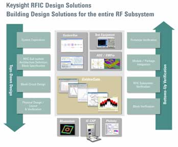
 GoldenGate RFIC Simulation and Analysis Software is an advanced simulation and analysis solution for integrated mixed signal RFIC designs that is fully integrated into the Cadence Analog Design Environment (ADE). GoldenGate is part of Keysight’s RF-IC simulation, analysis and verification solution that also includes Momentum for 3-D planar electromagnetic simulation, SystemVue & Ptolemy wireless test benches for system-level verification, and the Advanced Design System (ADS) Data Display for advanced data analysis. This suite links the RF system, subsystem, and component-level design and analysis as part of a unique and comprehensive RFIC design flow. GoldenGate is the most advanced simulation and analysis solution available for integrated RF circuit design. Its unique simulation algorithms are optimized for the challenging demands of today’s complex RF circuit design, enabling full characterization of complete transceivers prior to tape-out. To ensure device manufacturability and reduce design spins, GoldenGate takes advantage of both frequency-domain and time-domain simulation capabilities to perform necessary analyses on today’s RF devices. Keysight’s RF-IC simulation analysis and verification solutions include a series of products aimed at the design of large-scale RFICs used in wireless communication product design. Keysight’s GoldenGate plus EDA software provides industry-leading circuit simulation technology along with the leading 3-D planar electromagnetic (EM) simulator system-level simulation and design solutions for the performance of the circuits.
Eldo RF, Transistor-level simulator from Mentor Graphics
 The analysis and measurement capabilities of Eldo RF help designers verify complex RF IC designs more quickly and accurately. From simple compression or intermodulation analysis to complex digital modulation, Eldo RF powerful algorithms make genuine verification a reality. The Mentor Graphics® Eldo™ RF simulator provides the necessary performance and capacity breakthroughs for RF IC simulation, taking the baton where existing tools reach their limits. Consistently extending the capabilities of Eldo, the Mentor Graphics best-in-class analog simulator, Eldo RF provides a set of dedicated algorithms to accurately and efficiently handle the multi-GHz signals in modern wireless communication applications.
Virtuoso Multi-Mode Simulation from Cadence Design
The Virtuoso Multi-Mode Simulation release delivers an industry-leading Spectre circuit simulation platform for a comprehensive design and verification solution that provides SPICE, radio frequency (RF), FastSPICE, and mixed-signal simulators in a unique shared licensing package. This unified solution preserves the design intent and delivers scalable performance and capacity through reliable abstraction, providing robust verification of analog, RF, memory, custom digital, and mixed-signal silicon realization. The Spectre simulation platform delivers a variety of analyses and measurements in a flexible access model to provide designers with the appropriate simulation technology tailored for each abstraction level of
the verification flow. Spectre delivers a common infrastructure and an advanced database. It is fully integrated into Cadence’s Virtuoso® Analog Design Environment and Incisive® design and verification flow. The complementary feature sets of these simulation engines deliver improved productivity and facilitate adoption as designs move through the architecture, implementation, and verification stages—and as simulation needs change.


