FEATURES
- Ultra-wide 4:1 input voltage range
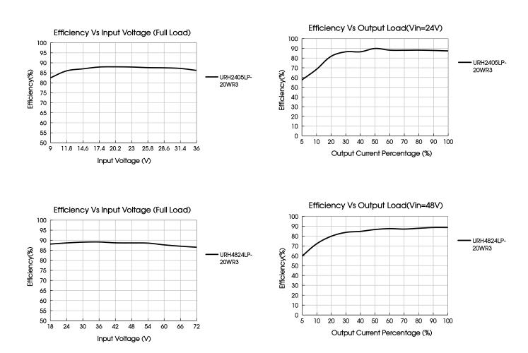
- High efficiency up to 89%
- No-load power consumption as low as 12W
- Operating ambient temperature range: -40℃ ~+85℃
- Reinforced insulation, I/O isolation test voltage 5k VAC, rated for 250VAC working voltage
- Transformer creepage 8mm, Transformer clearance 8mm
- Low leakage current < 5 µA
- Meets CISPR32/EN55032 CLASS A, without extra components
- Input under–voltage protection, output short–circuit, over-current, over-voltage protection
- Industry standard pin–out
- Meets 2xMOPP EN60601-1 third edition medical certification standard (Pending)
Meets EN62368 standard (Pending)
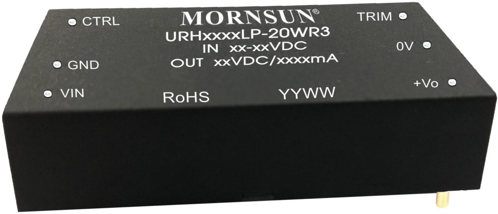
URH_LP-20WR3 series of isolated 20W DC-DC products with a 4:1 input voltage range. They feature efficiencies of up to 89%, 5000VAC input to output isolation, over-voltage, output short-circuit protection. They meet CLASS A of CISPR32/EN55032 EMI standards without extra components, meets EN60601-1 third edition medical certification standard (Pending). They are widely used in high isolation required area such as medical application.
| Selection Guide | |||||||
|
Certification |
Part No. |
Input Voltage (VDC) | Output | Full Load Efficiency (%) Min./Typ. | Capacitive Load (µF) Max. | ||
| Nominal (Range) | Max.* | Voltage (VDC) | Current (mA) Max./Min. | ||||
|
CE (Pending) |
URH2403LP-20WR3 |
24 (9-36) |
40 |
3.3 | 5000/0 | 83/85 | 10000 |
| URH2405LP-20WR3 | 5 | 4000/0 | 84/86 | 10000 | |||
| URH2412LP-20WR3 | 12 | 1666/0 | 84/86 | 4700 | |||
| URH2415LP-20WR3 | 15 | 1333/0 | 85/87 | 1600 | |||
| URH2424LP-20WR3 | 24 | 833/0 | 87/89 | 470 | |||
| URH4803LP-20WR3 |
48 (18-75) |
80 |
3.3 | 5000/0 | 84/86 | 10000 | |
| URH4805LP-20WR3 | 5 | 4000/0 | 85/87 | 10000 | |||
| URH4812LP-20WR3 | 12 | 1666/0 | 85/87 | 4700 | |||
| URH4815LP-20WR3 | 15 | 1333/0 | 86/88 | 1600 | |||
| URH4824LP-20WR3 | 24 | 833/0 | 87/89 | 470 | |||
| Note: * Exceeding the maximum input voltage may cause permanent damage. | |||||||
| Input Specifications | ||||||
| Item | Operating Conditions | Min. | Typ. | Max. | Unit | |
|
Input Current (full load / no–load) |
24VDC input | 3.3V, 5V output | — | 969/40 | 992/50 |
mA |
| Others | — | 969/8 | 992/15 | |||
| 48VDC input | 3.3V, 5V output | — | 479/20 | 490/30 | ||
| Others | — | 478/5 | 491/10 | |||
| Reflected Ripple Current | 24VDC input | — | 30 | — | ||
| 48VDC input | — | 30 | — | |||
| Surge Voltage (1sec. max.) | 24VDC input | -0.7 | — | 50 | VDC | |
| 48VDC input | -0.7 | — | 100 | |||
| Start-up Voltage | 24VDC input | — | — | 9 | |
| 48VDC input | — | — | 18 | ||
| Under-voltage Protection | 24VDC input | 5.5 | 6.5 | — | VDC |
| 48VDC input | 12 | 15.5 | — | ||
| Input Filter | Pi filter | ||||
| Hot Plug | Unavailable | ||||
|
Ctrl * |
Module on | Ctrl pin open or pulled high (3.5-12VDC) | |||
| Module off | Ctrl pin pulled low to GND (0-1.2VDC) | ||||
| Input current when off | — | 4 | 8 | mA | |
| Note: *The Ctrl pin voltage is referenced to input GND. | |||||
| Output Specifications | ||||||||
| Item | Operating Conditions | Min. | Typ. | Max. | Unit | |||
| Voltage Accuracy | — | ±1 | ±2 |
% |
||||
| Linear Regulation | Input voltage variation from low to high at full load | — | ±0.2 | ±0.5 | ||||
| Load Regulation① | 5%-100% load | — | ±0.5 | ±1 | ||||
| Transient Recovery Time |
25% load step change, nominal input voltage |
— | 300 | 500 | µs | |||
|
Transient Response Deviation |
3.3V③, 5V output | — | ±5 | ±8 |
% |
|||
| Others | — | ±3 | ±5 | |||||
| Temperature Coefficient | Full load | — | — | ±0.03 | %/℃ | |||
|
Ripple & Noise② |
20MHz bandwidth |
3.3V, 5V output | — | 100 | 200 |
mVp-p |
||
| URH2415LP-20WR3
URH2424LP-20WR3 URH4824LP-20WR3 |
— |
80 |
150 |
|||||
| URH2412LP-20WR3
URH4812LP-20WR3 URH4815LP-20WR3 |
— |
50 |
100 |
|||||
| Over-current Protection | 110 | 180 | 260 | %Io | ||||
| Over-voltage Protection | 110 | — | 160 | %Vo | ||||
| Short-circuit Protection | Continuous, self-recovery | |||||||
| Trim | — | ±10 | — | %Vo | ||||
| Notes:
①Load regulation for 0%-100% load is ±5% max.; ②Ripple & Noise of 3.3VDC/5VDC output converter for 0%-5% load is ±10% max; Ripple & Noise of other output converter for 0%-5% load is 5%Vo max. The “parallel cable” method is used for Ripple and Noise test, please refer to DC-DC Converter Application Notes for specific information; ③It is required connecting an external 270uF electrolytic capacitor for 3.3V output voltage model. |
||||||||
| General Specifications | |||||
| Item | Operating Conditions | Min. | Typ. | Max. | Unit |
| Isolation | Input–output Electric Strength test for 1 minute with a leakage current of 1mA max. | 5000 | — | — | VAC |
| Insulation Resistance | Input–output resistance at 500VDC | 10000 | — | — | MΩ |
| Isolation Capacitance | Input–output capacitance at 100KHz/0.1V | — | 40 | — | pF |
| Patient Leakage Current | 240VAC/60Hz | — | 3.6 | 5 | uA |
|
Reinforced Insulation |
Transformer creepage | 8.0 | — | — |
mm |
| Transformer clearance | 8.0 | — | — | ||
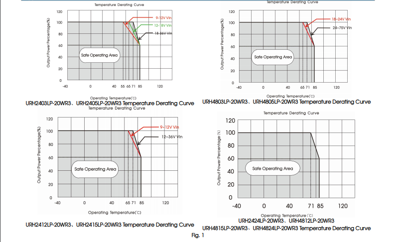
| Operating Temperature | See Fig. 1 | -40 | — | 85 | ℃ |
| Storage Humidity | Non-condensing | 5 | — | 95 | %RH |
| Storage Temperature | -55 | — | 125 |
℃ |
|
| Pin Soldering Resistance Temperature | Wave-soldering (Soldering time: 10s) | — | — | 260 | |
| Soldering spot is 1.5mm away from case for 10 seconds | — | — | 300 | ||
| Vibration | 10-150Hz, 5G, 0.75mm. along X, Y and Z | ||||
| Switching Frequency* | PWM mode(nominal input voltage, full load) | — | 280 | — | KHz | |
| MTBF | MIL–HDBK–217F@25℃ | 1000 | — | — | K hours | |
| Note:*Switching frequency is measured at full load. The module reduces the switching frequency for light load (below 50%) efficiency improvement. | ||||||
| Mechanical Specifications | ||||||
| Case Material | Black plastic; flame-retardant and heat-resistant (UL94-V0) | |||||
| Dimensions | 51.50 x 26.50 x 12.00 mm | |||||
| Weight | 27.0g(Typ.) | |||||
| Cooling Method | Free air convection | |||||
| Electromagnetic Compatibility (EMC) | ||||
|
Emissions |
CE |
URH2412LP-20WR3 | CISPR32/EN55032 CLASS A (without extra components), CLASS B (see Fig.3 for recommended circuit) | |
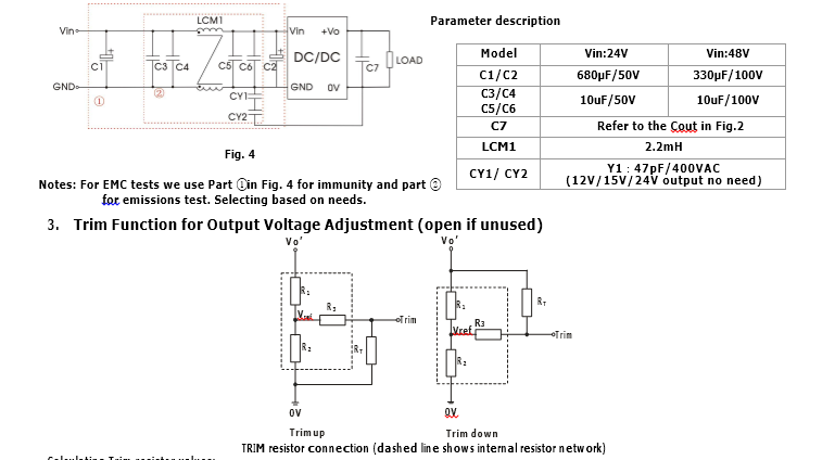
| Others | CISPR32/EN55032 CLASS A (without extra components), CLASS B (see Fig.4–② for recommended
circuit) |
|||
|
RE |
URH2412LP-20WR3 | CISPR32/EN55032 CLASS B (without extra components) | ||
| Others | CISPR32/EN55032 CLASS A (without extra components), CLASS B (see Fig.4–② for recommended
circuit) |
|||
|
Immunity |
ESD | IEC/EN61000–4–2 air ±15kV, contact ±8kV | perf. Criteria B | |
| RS | IEC/EN61000–4–3 10V/m | perf. Criteria A | ||
| EFT | IEC/EN61000–4–4 100KHz ±2KV (see Fig.4-① for recommended circuit) | perf. Criteria B | ||
| Surge | IEC/EN61000–4–5 line to line ±2KV (see Fig.4-① for recommended circuit) | perf. Criteria B | ||
| CS | IEC/EN61000–4–6 10 Vr.m.s | perf. Criteria A | ||
| PFM | IEC/EN61000–4–8 30 A/m, continuous | perf. Criteria A | ||
Typical Characteristic Curves
1.Typical application
All the DC/DC converters of this series are tested before delivery using the recommended circuit shown in Fig. 2.
Input and/or output ripple can be further reduced by appropriately increasing the input & output capacitor values Cin and Cout and/or by selecting capacitors with a low ESR (equivalent series resistance). Also make sure that the capacitance is not exceeding the specified max. capacitive load value of the product.

 4.The products do not support parallel connection of their output
5.For additional information please refer to DC-DC converter application notes on www.mornsun-power.com
Dimensions and Recommended Layout
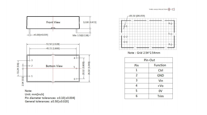 Notes:
- For additional information on Product Packaging please refer to mornsun-power.com. The Packaging bag number: 58210039
- The maximum capacitive load offered were tested at input voltage range and full load;
- Unless otherwise specified, parameters in this datasheet were measured under the conditions of Ta=25℃, humidity<75%RH with nominal input voltage and rated output load;
- All index testing methods in this datasheet are based on company corporate standards;
- We can provide product customization service, please contact our technicians directly for specific information;
- Products are related to laws and regulations: see “Features“ and “EMC“;
- Our products shall be classified according to ISO14001 and related environmental laws and regulations, and shall be handled by qualified


