This circuit is an extension of the 1-watt LED Driver project.
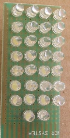
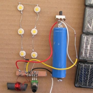
It is a very clever circuit and will illuminate up to six 1-watt LEDs or 30 white LEDs to give an overall illumination of about 1 watt.

The 1-watt LEDs are not driven to full brightness but this circuit gets the best illumination from a single 3.7v cell or 3 x 1.2v cells or even a damaged 6v rechargeable battery with only two good cells.
Not only can you use any type of cell or battery for the supply but the circuit will also charge the cell or battery from any type of solar panel or set of solar cells.
A normal solar cell produces 0.55v but many cells produce 0.45v or less and if you have a damaged panel or set of cells that produces any voltage from 4v to 6v, you can use them in this project.
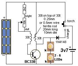
The slide switch changes from CHARGING to ILLUMINATION and uses the same “step-up” fly-back circuit for both charging and illumination.
To charge a 3.7v Li-ion cell requires a voltage up to about 5.5v from a solar panel to overcome the “floating voltage” produced by the cell when charging and a “head” voltage so the cell will be charged.
But with this circuit you only need 4v supply and the circuit will increase this to deliver the ENERGY to the cell.
 With a supply as low as 4v, the unloaded output is over 12v, but the voltage gets “clipped” at slightly higher than 3.7v (the charging voltage) and the current from the inductor is passed to the cell via the high-speed diode.
You cannot measure the charging current directly so put a 100R across the panel with 100u across it and feed it via a 1N4148 diode. Measure the voltage across the 100R.
Each volt is equal to 10mA. Thus: 5v equals 50mA.
This indicates the solar panel is working and will deliver a current to the battery.
The project is much-more efficient when many LEDs are connected in series and not driven to full brightness.
You can test this by putting 6 in series then “shorting-out” two LEDs. The illumination will decrease due to the absence of the two LEDs, but the current taken by the circuit will remain the same.

If using a 3.7v cell, the 1k resistor in the previous project will need to be increased to 2k2 to keep the current below 200mA to conserve the battery.
An illumination panel of up to 30 LEDs can be made with 6 strings of 5 LEDs in each string.
No dropper resistor is needed as it will waste energy and although this is not normally done, it is possible to connect strings of LEDs in parallel if the characteristic voltage drop across each string is the same.
You can match up each string by measuring the voltage across each LED or turn ON the panel and see if all the LEDs are producing the same brightness.
The minimum number of LEDs is 15 for this circuit and should be spread apart to get the maximum amount of coverage.
The 3.7v cell can be taken from a faulty laptop battery. Only some of the cells will be faulty in the battery and you can use the good cells for this project.


