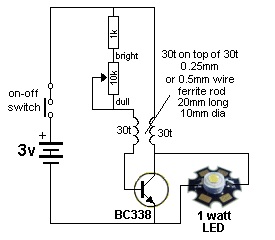
This circuit will drive a 1 watt LED from 1 or 2 cells (commonly called “dry cells”).
The circuit consists of only 4 components plus a LED and the secret to its operation is the transformer. It is operated in FLY-BACK mode and this causes it to produce a large voltage when it is turned off quickly during part of each cycle.
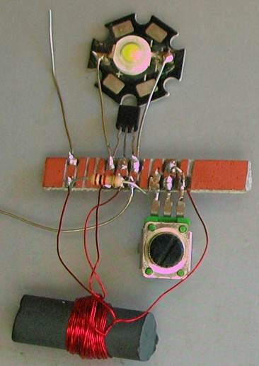
The transformer can be made from any piece of ferrite material and the number of turns and wire-size are not critical.
 You can use a piece of broken antenna rod from an AM radio or the core from an inductor in a computer power-supply. The size is not important, but obviously the largest size will provide the highest output.
The wire can be from 0.25mm to 0.5mm and we have selected 30 turns for each winding so you don’t have to remember which is the primary and feedback winding.
The circuit will operate from a single cell, down to less than 0.8v but it is much better to use 2 cells so you can adjust the brightness via the 10k pot.
When the pot is at 10k, the current is approx 50mA and it increases to 200mA when the 1k resistor is feeding the base.
The best part of the project is making the transformer and realizing it will convert a low voltage to a higher voltage to drive a powerful LED.
The output of the transformer is over 25v when the LED is removed, but this voltage, combined with the current it produces, illuminates the LED very efficiently.
The LED only allows a voltage up to 3.6v to appear across it as this is the characteristic-voltage for the crystal used to produce white light.
As soon as this voltage is reached, the energy from the transformer is converted to CURRENT.
 The LED is actually across the primary winding via the battery, with the battery in SERIES.
The lead connected to the collector of the transistor produces a voltage HIGHER than the supply rail when the transformer is rapidly turned OFF during part of the cycle.
This is due to the collapsing magnetic flux cutting the turns of the winding.
If the voltage of the supply is 3v, the transformer only has to produce 0.6v and the energy from the magnetic flux is converted to CURRENT.
This means a very high current flows for a short period of time. The LED is very fast to respond to this current-flow and that’s why it will produce a high brightness.
The transistor must be BC337 or BC338 with a collector current capability of 500mA or more. A BC547 or 2N2222 will not be suitable.
Build the circuit by soldering the components on a small piece of copper-clad board cut into strips, making sure none of the wires touch each other.
Solder the batteries together and use a clip to connect the battery to the circuit.
Connect the LED to hook-up wire and place it above your workbench so it can be turned ON when a black-out occurs. The project will also drive up to fifteen 5mm LEDs in parallel (20,000mcd) to produce a wider dispersion of light.
The supply MUST NOT be higher than 3.6v as the circuit is a BOOST CIRCUIT and will increase a supply voltage (from 0.9v to 3.6v) to drive the LED. It does not have any current-limiting resistor and therefore a supply above 3.6v must NOT be used.


