New to Emma? Emma is a public-domain reference design for an imp-powered device from Electric Imp.
Really wonder! “The Imp” is a tiny wifi-connected microcontroller packed up in the same form factor as an SD card. It’s really easy to build imp-powered things, and once it’s built you can connect your device to any wifi network and interact with it from anywhere in the world. Check out the imp if you haven’t before digging deeper: http://electricimp.com/
Devices that are powered by or enabled to work with an Electric Imp are called “impees” (just like one who is employed is an employee).
Schematic Overview

Since Emma is a public domain reference design, anyone can take the schematics, gerber files, or bill of materials (BOM) and use them to order everything needed to build more Emmas. This is the case no matter how many Emmas you might want to make. Want to build a whole production run and sell them? Totally fine. Want to make some changes to they layout or tweak the design to add your own feature or twist? By all means, please do.
The pdf of the Emma design is attached to this step in addition to the screen shots shown. The full project source for this design is available from the Electric Imp Dev Center. Note that many other reference designs are also available at on the Reference Designs Page.
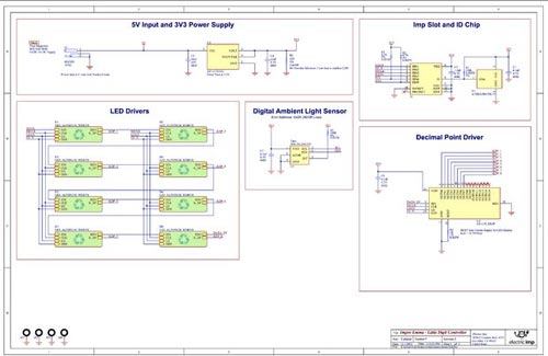
Emma’s design consists of four functional blocks: the power supply, the imp slot and ID chip, the LED driver and digit circuit (which is repeated 9 times in the design), and a digital ambient light sensor which was added just for some extra flair. The light sensor can be excluded without any ill effect (except, of course, that you won’t be able to view the light level from anywhere in the world).
Emma’s power supply uses the Texas Instruments AP1117E33G LDO to obtain a 3.3V supply from the board’s 5V supply voltage – the imp, as well as the driver ICs for each digit, require a 3.3V supply. This LDO is inexpensive and easy to solder, and is a new addition in revision two of this design.
Note the Atmel ATSHA204-TSU-T part at U2, in the “Imp Slot and ID Chip” section. This part is an ID chip which provides the impee with a unique ID number. This number is used when the imp comes online and registers with the Electric Imp cloud; this is how the Imp Cloud knows what firmware to provide to the imp when it comes online. This part can be purchased and installed right off-the-shelf; no special initialization or configuration is needed. Just solder it down and you’re good to go.
The Taos 856-TSL2561FN is a simple I2C sensor which can be used to detect the ambient light level around the impee. As shown on the schematic, this part has I2C slave address 0x29. Source code to read the sensor is included in this tutorial.
Let us study the circuit which controls each display digit.
Emma Display Digits and Drivers

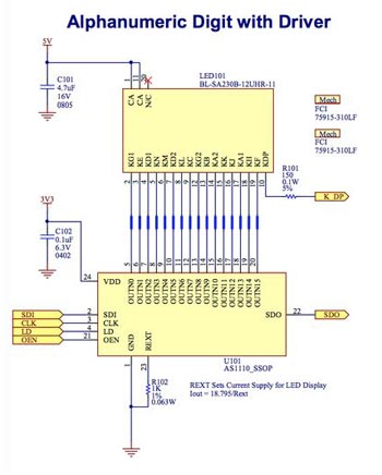
Each display digit has 17 segments, with 16 of those segments being part of the alphanumeric display and the 17th segment being the decimal point. For simplicity in software, each digit has its own display driver part for the alphanumeric segments, while all of the decimal points are controlled by another driver, for a total of 9. The driver used is the Austria Micro AS1110. This part was selected because it combines the the function of a serial shift register and a low-side current sink driver for the LED display into a single chip, which makes Emma’s layout a lot simpler and construction a lot easier. This part is capable of sinking over 2A per chip – far more current sinking ability than we need for a single display digit!
The AS1110 is a constant-current driver, and the current through each segment is controlled with the selection of a single resistor on each AS1110, Rext. Each display digit is rated up to 20 mA per segment, and Rext is selected so that each display segment will run at approximately 18 mA. Emma is quite bright! A piece of tinted plexiglass in front of the display digits can provide a higher contrast ratio without sacrificing too much brightness, for a really good visual effect.
Because the AS1110 is, functionally, a serial shift register, data is clocked through each digit. In software, this is accomplished by writing out a 9-byte binary blob on the single serial data out line. The first byte out controls the decimal points, the second out controls the left-most digit, and so on.
In addition to the clock, serial data in, and serial data out pins, the AS1110 has a load pin and an output enable pin. The load pin is toggled high to load the data into the output stage of the driver after shifting data in with the serial data in and clock lines. The new data will be displayed immediately if the output enable line is asserted (output enable is active-low, so the line is driven low to assert). Note that toggling the load pin high clears the input stage of the driver, so the old-school-calculator effect obtained by shifting data through the driver with the output enabled is not possible with this driver.
The output enable line provides a handy way to control display brightness, as well as allowing for fade-in and fade-out effects, by driving the line with a pulse-width modulated signal.


