
By Derek Hu, Pico Technology
About Power Rail Noise
Power Ripple is a very common concept for electric engineers. Usually, it’s one of the indicators to evaluate the output stability of a power supply. The test points are always near to the power supply (For example, VCC and GND of the VRM in Figure 1) and 20MHz bandwidth limiter is always used to remove the noise with higher frequency which usually comes from other parts of the system.
However, the chips in a circuit care about the voltage in its pads. Figure 1 below shows a simplified diagram of a four-layer PCB. The top and bottom layers are signal planes and the middle two layers are power plane and ground plane. The VRM (Voltage Regulator Module) is used to power the Chip. It outputs a voltage, marked as V1 across its VCC pad and GND pad, which connect to the VCC and GND pads of the Chip accordingly through the power plane and ground plane. The voltage across VCC pad and GND pad of the Chip is marked as V2. The aim is to make V2 equal to VRM’s output, V1. But there’s a path between VRM and Chip. We can call this path the power rail (or PDN interconnects), which is showed in figure 1 with dotted lines. Any current flow due to I/O switches, crosstalk, EMC, will cause voltage fluctuation in V2 because of the impedance in the power rail. We call this voltage fluctuation the power rail noise. The frequency components of power rail noise can be up to a few hundred MHz or even 1GHz. A variety of components especially capacitors in the PDN are used to provide the low impedance power rails for the noise with various frequencies in order to reduce the fluctuation.
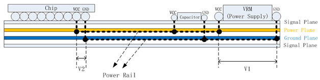
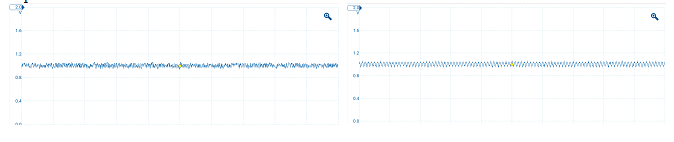
Figure 2 below shows two typical kinds of power rail noise. One is random noise, the other one is periodic noise. Sometimes there will be also transient noise.
Challenges of power rail noise measurement
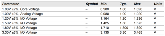
The increasing functionality, higher density, and higher frequency operation of many modern electronic products have been driving the need for lower supply voltages. It is common for high performance processors to have DC supplies as low as 1.0 volt, and tighter tolerances. It’s getting difficult to meet the tighter tolerance requirements of low voltage power supplies due to a number of factors like higher frequencies, faster rise times, increased crosstalk, which makes the power rail noise getting worse and complicated. As a result, it has become increasing challenge for the design engineers to test and analyze power rail noise for the electronic products with leading technologies like mobile phones, AI products, electronic game players. Figure 3 shows the power supply specifications of a high-performance processor. We can see the core voltage has the specification of 1.00V+/-2%. The allowed voltage fluctuation is -20mV to 20mV. This requires the test system to have proper bandwidth, lower noise, higher resolution, as well as bigger DC offset.
Let’s take a look at what kind of oscilloscope and probe we should select to test the low voltage power rail noise of a high-performance processor like FPGA/GPU/CPU in a modern electronic system.
Firstly, we shouldselectan oscilloscope with right bandwidth.
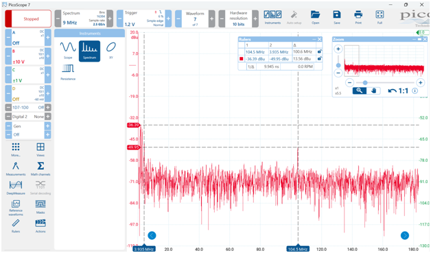
As a rule of thumb, most of the fast high-performance processors include package filtering, which generally can constrain the frequency of the noise from the processor to a few hundred MHz. An oscilloscope with the bandwidth not less than 1GHz is enough for most cases. But we should evaluate the whole system carefully in case there are other circuits which leads to the power noise with higher frequency. Be aware to select the oscilloscope with right bandwidth since the measurement noise of an instrument is getting bigger as the bandwidth increases. Spectrum instrument function in an oscilloscope can be used to check the frequency components in a power rail noise. Figure 4 below shows the spectrum instrument function in PicoScope 7 software.
Secondly, we should select an oscilloscope with higher resolution and bigger DC offset.
1) Higher ADC resolution leads to smaller quantization error so that the noise on an DC voltage can be distinguished more clearly and measured more accurately. Figure 4 and figure 5 shows a comparison of 8-bit capture with PicoScope FlexRes and 12-bit capture with PicoScope FlexRes.
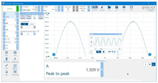
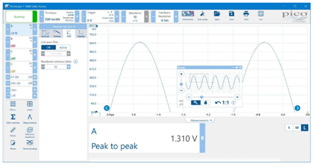
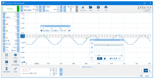
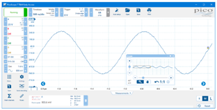
2) Bigger DC offset allows you to add an adjustable voltage to the input signal to cancel out any unwanted offset. The resulting signal will then fit within a smaller input range of the scope, allowing it to benefit from the full resolution and accuracy of the ADC.Figure 6 shows a 1V p-p sinewave captured on the ±20 V range. When it’s zoomed in, the poor resolution with almost 180 mV between ADC levels can be seen.In figure 7 we use the DC offset adjustment to add a –10 V offset on the ±5 V range. We can hardly see the quantization steps.
Thirdly, we should select a probe to work with the oscilloscope.
The probe should be high input impedance relative to the output impedance of the power rail to reduce the impaction on the circuit. A power rail for low voltage power-supplyis usually a pair of adjacent and tightly coupled planes with various of capacitors connected across them to provide very low impedance of less thandozens of mΩs. In this case, even a coaxial connection with 50 Ωs input impedance works.
And low gain of a probe is also meaningful to lower the noise of a testing system.A coaxial connection with 50Ωs coupling of an oscilloscope can provide 1:1 gain.
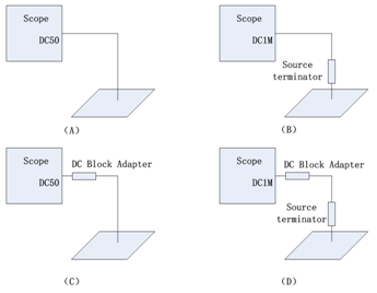
So, a coaxial connection is one of the choices for power rail noise measurement in the case of low amplitude like 1.0V around and low output impedance like mΩs range. The connection in Figure 8 (A) is preferred if the scope has enough DC offset. Or an external DC Block Adapter with proper combination of capacitors can be used to remove the DC offset before the DC power signal goes into the scope, as shown in Figure 8(C). Sometimes using DC1M coupling in the scope can avoid the potential damage of scope due to the high amplitude of voltage or current of a DC power-supply signal, but a source terminator is required to remove the reflection caused by the mismatch between coaxial cable’s impedance and scope’s input impedance in this case, as shown in Figure 8 (B) and (D).
Test power rail noise with PicoScope
Figure 9 below shows a power rail noise waveform of a GPU tested with PicoScope 6424E and PicoScope 7 software. PicoScope 6424E is an oscilloscope with 500MHz bandwidth, 8~12 bits flexible resolution, 5GS/s sampling rate, 4GS memory, DC analog offset of ±1.25 V (±10 mV to ±1 V ranges)and ±20V (±2V and ±5V ranges) with 50 Ω coupling. A test fixture and a coaxial cable are used for the measurement and it’s a batch test in manufacture lines. PS 6424E works with 12bits hardware resolution, +/-20mV range, DC50Ω coupling and -210mV offset.
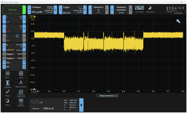
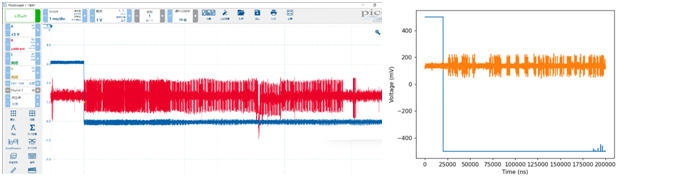
Figure 10 below shows another power rail noise waveform tested with PicoScope 6424E and active differential probe AD 2801. AD 2801 is an active differential probe with 800MHz bandwidth and +/- 15V testing range. The amplitude of the power-supply signal under test is about 3.3V so a -3.1V DC offset is set in order to make the scope work with +/-500mV range. The left of Figure 10 is the waveform acquired in Python with PicoScope 6424E.
Why PicoScopes?
PicoScope 6424E are popularly used for power rail noise measurement in automated testing systems and during the process of research and development because of its excellent performance like flexible/high ADC resolution (8bits~12bits), deep memory (up to 4GS), fast data transfer rate (up to 325MS/s in streaming mode) and easy-to-ingrate features like high cost-efficiency, small size, comprehensive SDK.
The main reasons that people like to integrate PicoScopes into their automated testing systems for power rail noise measurement are the unique advantages and powerful capabilities of PicoScopes.
- High reliability
Established in 1991, Pico Technology has been focusing on the development and manufacture of PC-based test instrument and data acquisitionequipment.Decades of product iteration and stringent quality controls make PicoScopeshighly reliable.
- Cost-efficiency
Different from benchtop instruments, the fact that PicoScopes don’t have PC in the box gives them more unique hardware advantages due to the simple structure, including high bandwidth/sampling rate, deep memory, high/flexible ADC resolution, multiple analog and digital inputs, fast speed, etc. The use of full capability of an external PC allows PicoScopes moresoftware capabilities,including 30+ serial decoders, advanced math functions (FFT, filters, measurements plotting, etc). Moreover,dozens of PicoScope models make the customers easier to pick one affordable and suitable for their applications.
- High/Flexible ADC resolution
PicoScopes offer a wide range of vertical resolution options from 8 to 16 bits. The higher the resolution, the greater the vertical accuracy and the dynamic range. The flexible resolution feature in PicoScopes is based on Pico’s breakthrough ADC technology which allows users to switch from 8 to 16 bits in one unit.
- Fast and powerful SDK
PicoScopes provide a level of interconnectivity and customization that is not usually available on most benchtop oscilloscopes. The SDK(Software Development Kit) allows users to create custom applications for their particular projects. That makes PicoScopesgo beyond just being a regular oscilloscope. PicoScopes running under SDK have much better performance. For example, it can acquire and transmit data continuously to PC with the speed up to 312 MS/s; The memory can be segmented up to 2 million; The users can set the advanced triggers and generate waveforms programmatically. Programming with SDK is simple and easy. Professional technical support is always ready and lots of code examplescan be found in github.com/picotech.
All Pico products including PicoScopes come with a free-of-charge SDK. The SDK includes drivers for Windows, macOS, Linux and Raspberry Pi (ARM7). It allows users to write their own software to control the instruments with popular languages such as C, C#, C++, Python, MATLAB, LabVIEW and Microsoft Excel.
- Compact and portable units
Unlike traditional benchtop instruments, PicoScopes are compact, light and portable. When used with a laptop computer, a PicoScope allows you to carry a complete electronics toolset in one bag with your PC. And small size also makes PicoScopes easier to be integrated into the systems with almost no increase in weight or size.


