PicoScopes are high-quality oscilloscopes available with a range of resolutions from 8 bits to 16 bits. The highest-resolution models have the greatest accuracy, but you can get great results from any model of PicoScope with careful use of the PicoScope 7 software. Here we demonstrate a combination of software and hardware features that you can use to optimize your measurement accuracy.

Enable Resolution Enhance
Ever wished your scope had higher resolution? Maybe 8-bit resolution was good enough for your digital debugging, but today you need to make some more accurate measurements on an audio amplifier. With PicoScope 7 you can switch on a signal processing feature called Resolution Enhance to gain
up to four extra effective bits. The results are impressive but you need to be aware of the potential effects on measurement accuracy and frequency response. Resolution Enhance in PicoScope 7 is produced by a digital
moving-average filter that smooths out high-frequency components of the input, including quantization error and noise, to generate higher effective resolution (technical details). In many cases the attenuation of high frequencies is not a problem, because your PicoScope probably has a higher hardware sampling rate and bandwidth than you need to capture your
signal accurately. You can often just increase the sampling rate to reduce the lowpass effect of the filter. For medium to low-bandwidth signals, Resolution Enhance delivers higher effective resolution with very little distortion of the signal.
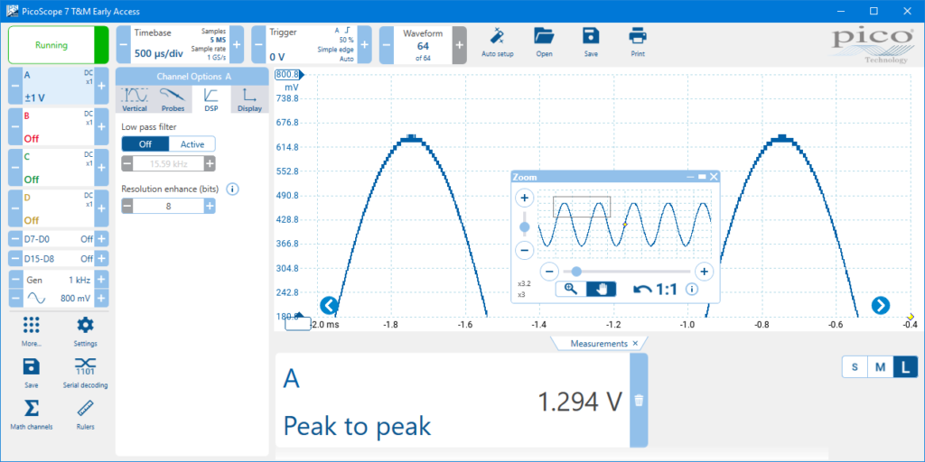
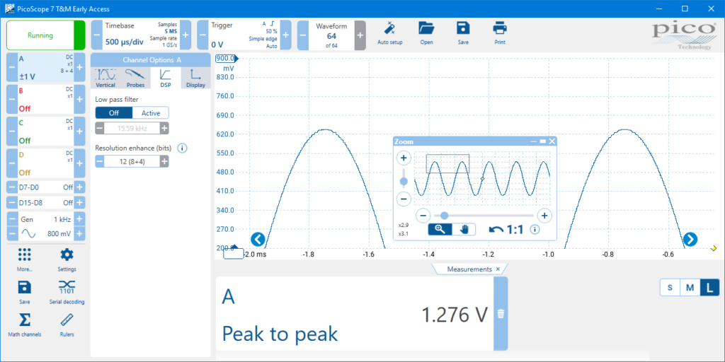
Here’s an example of a peak-to-peak measurement first without, and then with, Resolution Enhance at an input frequency of 1 kHz. You get a much cleaner waveform with a more accurate measurement:
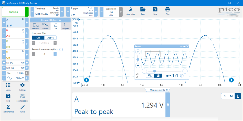
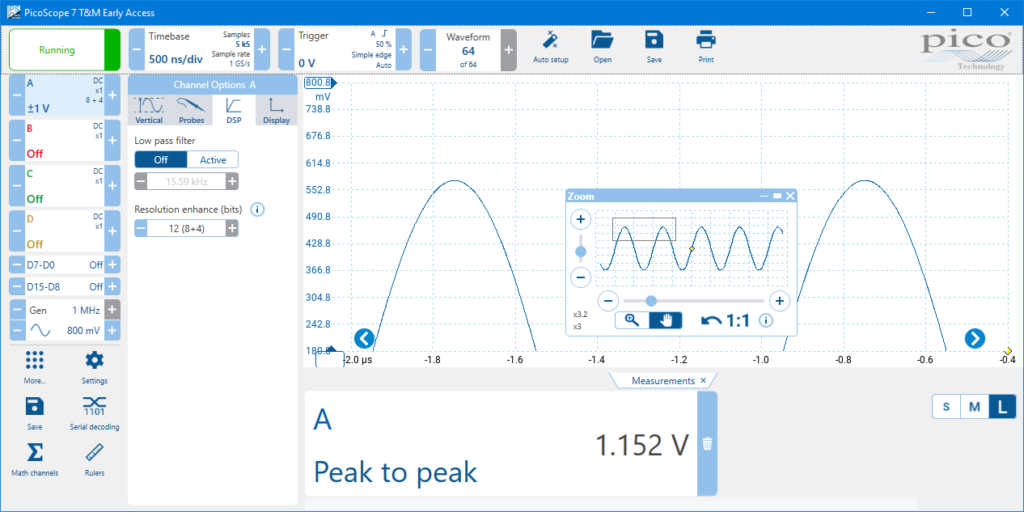
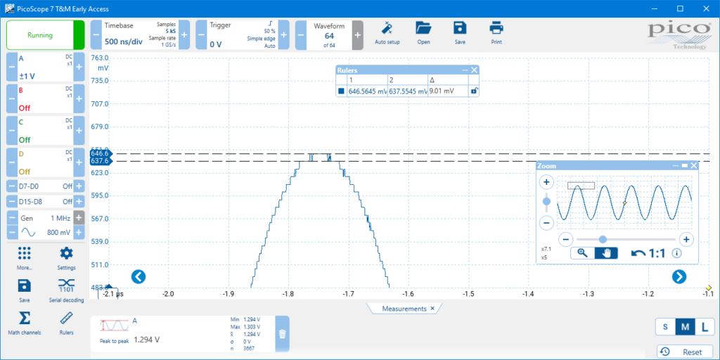
Resolution Enhance is less suitable, however, for use on high-frequency signals that require high sampling rates to capture correctly or that have high-frequency components that you wish to preserve. In the examples below, we’ve increased the input frequency to 1 MHz. You can see a significant error caused by the lowpass filtering effect of Resolution Enhance:
Resolution is not the same as accuracy, of course. Resolution Enhance allows you to measure smaller signal changes, but the accuracy of the measurements indicated by PicoScope 7 cannot be better than the accuracy of the scope’s hardware. Check the accuracy specifications, including gain accuracy and offset accuracy, in your scope’s data sheet.
Use FlexRes® flexible resolution
FlexRes® is a hardware feature available on all scopes in the PicoScope
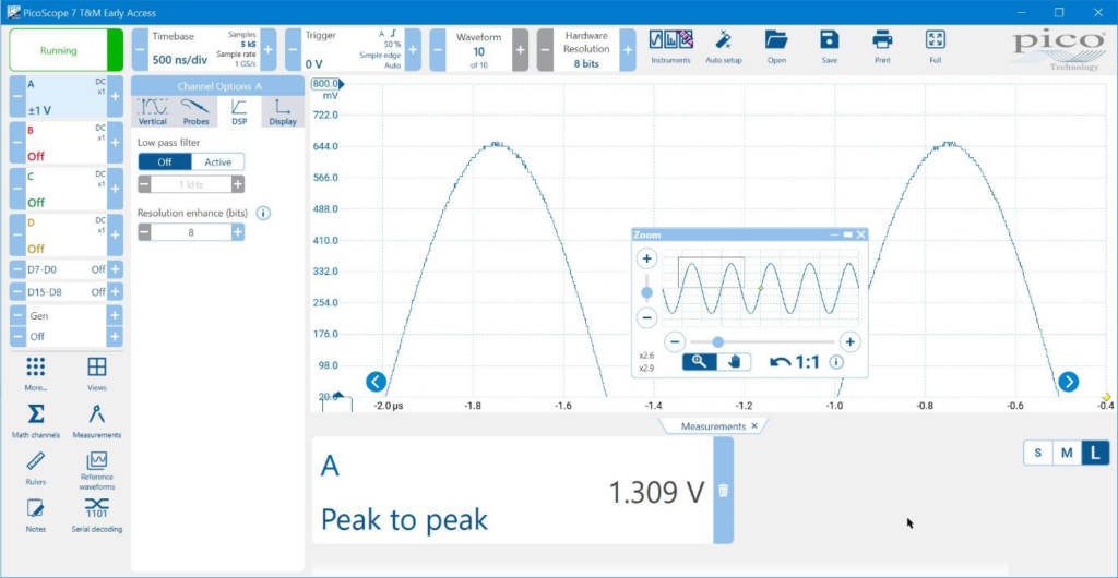
5000D Series, as well as selected scopes in the PicoScope 4000 and 6000E Series. Unlike Resolution Enhance, FlexRes involves no digital filtering and therefore has less of an effect on high-frequency signals. See your scope’s data sheet for the effect that FlexRes has on sampling rate and memory depth. Depending on the scope model, the range of resolutions can be as wide as 8 bits (suitable for working on highspeed logic) to 16 bits (precise enough for high-fidelity audio). FlexRes works by combining multiple high-resolution ADCs (analog-to-digital converters) – see What is FlexRes? for more details. It gives you the benefits of high sampling speeds and high resolution combined in a single oscilloscope. Here’s an example showing the superiority of FlexRes over Resolution Enhance. First, we’ll capture a 1 MHz sine wave at 8-bit resolution:
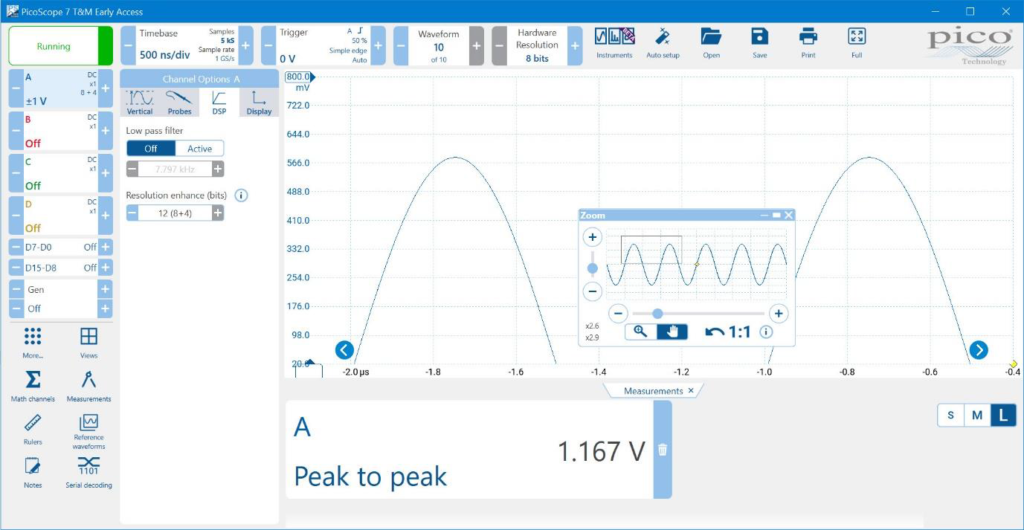
Next, here is the same signal with the 8-bit hardware resolution software-enhanced to 12 bits. It’s clean but no longer accurate, as the measured amplitude has dropped by 11%:
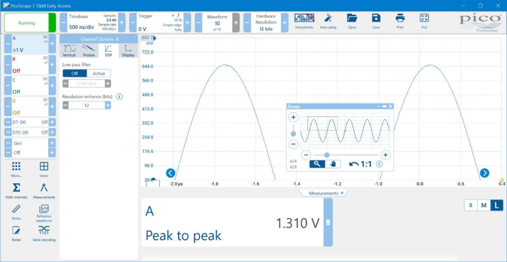
Finally, here is the result of switching on FlexRes with 12-bit resolution. We now have a clean signal and the amplitude measurement has returned to its correct value:

Select the right voltage range
Dynamic range is simply the range of voltages that your scope can measure, from the highest to the lowest. Like most scopes, PicoScopes have a symmetrical dynamic range, so if the highest voltage at a particular range setting is +1 V then the lowest will be –1 V. We call this range ±1 V. If you want the best accuracy, don’t leave your scope set to its highest range. This may be more convenient than frequently changing ranges but it is a waste of your scope’s capabilities. Take an 8-bit scope, for example. Its ADCs can distinguish no more than 256 (28) possible voltage levels. Table 1 shows the
ideal voltage resolutions you can expect from this scope on its ±20 V range compared to its ±1 V range.

In practice the scope gives slightly coarser voltage resolution than the ideal figures in our table, as some of the ADC’s range is reserved for internal adjustments. The waveforms below show the effect of differing voltage ranges on a sub-1-volt amplitude sine wave signal.
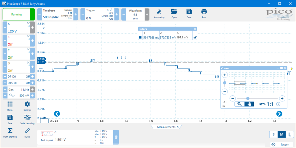
The lesson from this is to select the lowest voltage range that fits your signal. PicoScope will even do this for you if you set the range to Auto. Don’t worry about overloading your scope: as long as the input is within the specified maximum voltage range to avoid damage (including any restrictions on 50 Ω inputs, if your scope has them), selecting the wrong range will not harm the instrument. Note on auto-ranging: PicoScope 7 has continuous auto-ranging, similar to that on a digital multimeter, which repeatedly adjusts to the smallest voltage range that fits the signal. This
allows hands-free operation. Many competing scopes only have single-shot auto-ranging, requiring you to press a button each time the signal amplitude changes.
Use auto-arrange
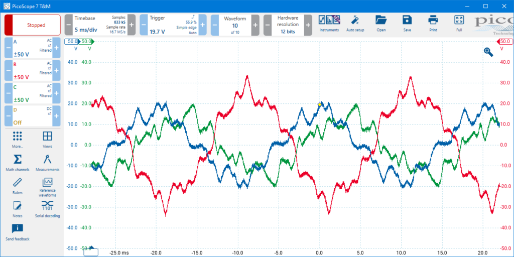
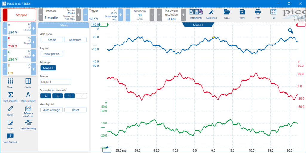
To make traces from multiple channels fit the display, use PicoScope 7’s Views > Axis layout > Auto arrange function. This changes the displayed scale of the traces without altering the input ranges that you have chosen. The resolution and accuracy stay the same even if the traces appear smaller. To reveal extra detail, simply zoom in.
Remove any DC offset
Measuring a signal with a large DC offset can be a challenge. Such signals are common in power supply circuits, for example, where you might be interested in a gate switching pulse fed to a high-side transistor – that is, one attached to the positive rail. If you feed the signal directly into a simple oscilloscope, you will need to select a high voltage range to include the
offset. The pulse will then occupy a small fraction of the input range, making it difficult to measure accurately. Two techniques to get around this problem are:
- AC coupling
- DC offset adjustment

Almost all scopes have an AC coupling mode. Just press a button and the DC offset disappears, allowing you to use the whole input range to see the pulse or other signal features. Problem solved, right? Not quite. First, you have lost all information about the DC offset. What is its magnitude? Is it stable? You have no idea unless you switch back to DC coupling and a higher range. This can be a safety issue if you decide to connect the signal to another instrument and exceed its maximum input range without realizing. Second, AC coupling is not perfect – it lets through low frequencies, just at a lower amplitude. So any drift in the DC offset will disturb your AC-coupled signal slightly, adding errors to your measurements.
This brings us to DC offset adjustment, which is a valuable feature available

on better scopes. It allows you to add an adjustable voltage to the input signal to cancel out any unwanted offset. The resulting signal will then fit within a smaller input range of the scope, allowing it to benefit from the full resolution and accuracy of the ADC.
Adding an offset to your signal can introduce further errors, so it is important to include these in your calculations. Pico publishes detailed specifications on the accuracy of the DC offset adjustment function – see the data sheet for your oscilloscope. Also check this data to make sure that your scope has a sufficient offset adjustment range for your application.
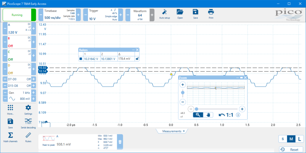
Here’s an example of a signal with a large DC offset and how it looks with AC coupling and then with DC offset adjustment. First, we’ll capture it on the ±20 V range. When we zoom in, we can see the poor resolution with almost 180 mV between ADC levels:
Next, here’s the same signal with AC coupling, allowing us to reduce the input range to ±1 V. We have eliminated the large quantization steps, but there is nothing to tell us about the hidden 10 V DC offset:
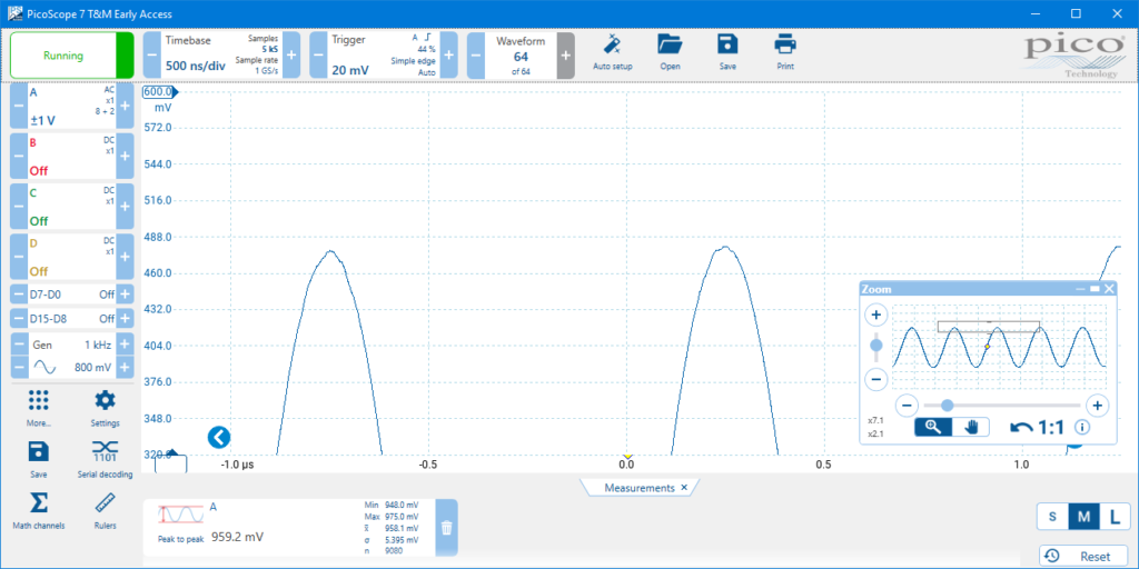
Lastly, we’ll use the DC offset adjustment to add a –10 V offset. We had to switch to the ±5 V range because the PicoScope 3000D Series scope can’t provide this degree of offset on the more sensitive ranges. With a larger budget, we could have used a PicoScope 6000E Series scope to give us the desired offset on the ±1 V range. Nevertheless, even on this range we can hardly see the quantization steps:
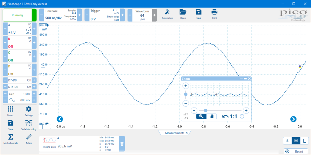
The channel button reminds us of the offset we’ve applied. We can use this to calculate the voltage of the original signal:

As you can see, DC offset is a valuable feature that does more than just moving the traces
around on the screen.

Choose a Deep Memory scope
So far, we have discussed amplitude accuracy, but what about timing accuracy? PicoScope 7 can measure numerous time-domain parameters such as pulse width, rise time and frequency, and to get the best results it’s important to choose the right scope and set it up correctly. Deep Memory is an important aid to obtaining accurate timing measurements. PicoScope Deep Memory scopes have capture buffer sizes ranging from hundreds of mega samples up to several giga samples. Deep Memory allows the scope to keep sampling at its highest rate even on long time bases, allowing you to make high-resolution timing measurements on long duration waveforms. Without Deep Memory, your scope will be unable to use its highest sampling rate on longer timebases and timing resolution will be
degraded. Consider the PicoScope 6000E Series Deep Memory scopes, for example. These instruments have a top sampling rate of 5 GS/s, giving a timing resolution of 200 ps. They also allow single captures of up to 1 GS using the PicoScope 7 software. Therefore, you can capture a waveform of up to 200 ms duration at the maximum sampling rate and still measure timing details with 200 ps resolution. As with amplitude accuracy, timing accuracy is only as good as the hardware accuracy of your scope. Consult the data sheet for specifications of timebase drift and jitter. Deep Memory also has an effect on amplitude measurements. If your scope’s sampling rate is too low, the waveform will be distorted and amplitude measurements will be inaccurate.
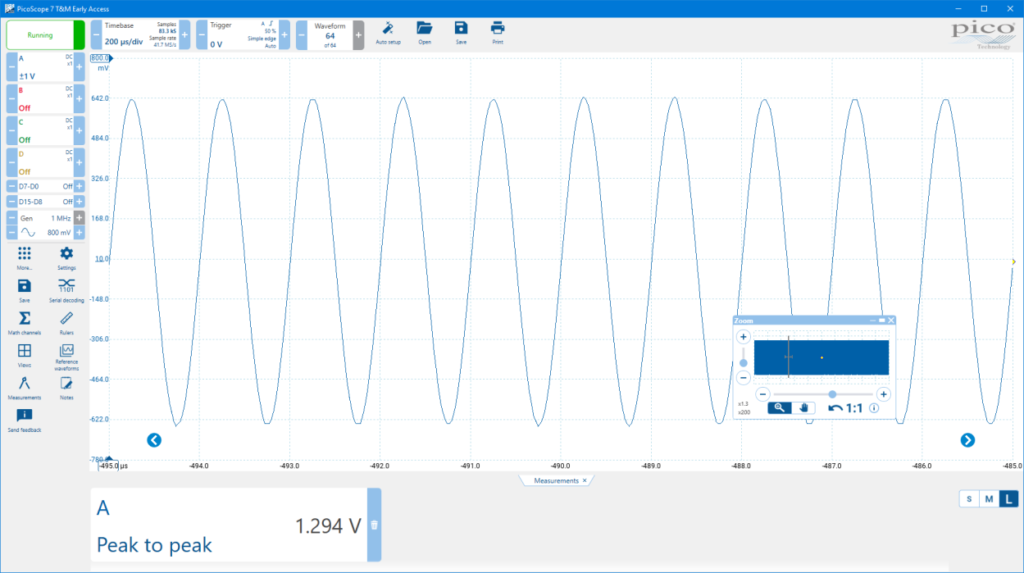
In the following sequence of examples, we measured the peak-to-peak voltage of a 1 MHz sine wave. We began with a fast 200 μs/div timebase so that the wave shape was accurately captured. Any basic scope can do this, even a cheap one with a short capture memory. To prove it, we simulated a short-memory scope by limiting the capture buffer in PicoScope 7 to 100 kS. PicoScope measured the correct peak-to-peak voltage:
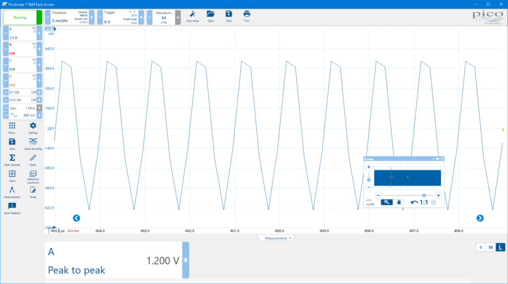
Next, we decided to make a longer capture—perhaps we were looking for long-term sags or dropouts in the waveform—so we slowed the timebase to 2 ms/div. Because of the capture memory limit, the scope was forced to sample more slowly, at only 5 MS/s, so the waveform was distorted and a significant error appeared in the peak-to-peak measurement:
Finally, without changing the timebase, we removed the 100 kS capture buffer limit, allowing the PicoScope to use its deep memory. This restored the waveform to its correct shape and eliminated the peak-to-peak measurement error:
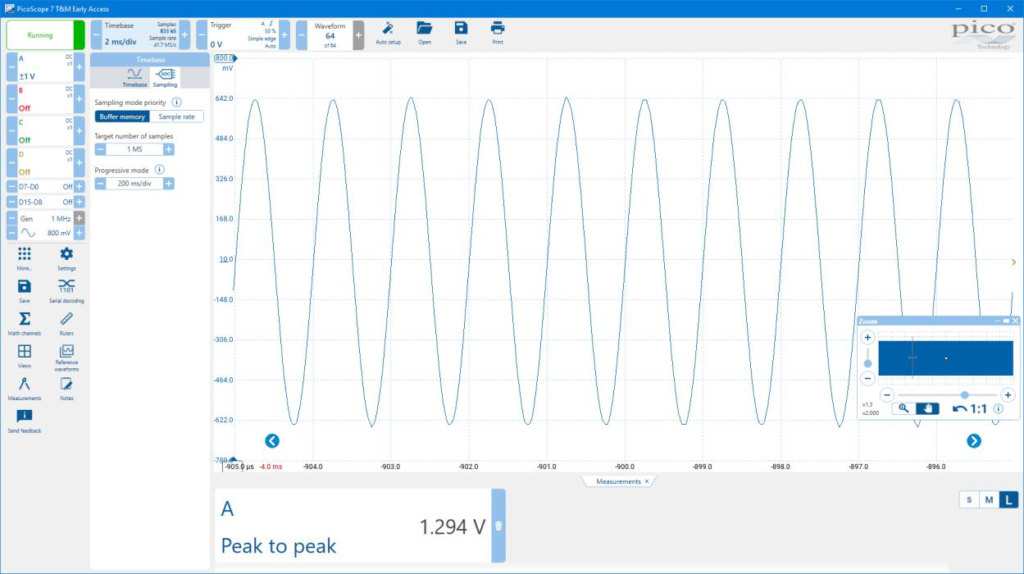
This demonstrates that the Deep Memory in the majority of PicoScopes helps to maintain accuracy, especially on longer timebases.

Conclusion
PicoScope 7 is taking over as the new standard software for PicoScope oscilloscopes. It has all the features you need for making accurate
measurements and is easier to use than its predecessors. As you can see, there is much more information on the display so you need to do less
searching in menus. Whether you have a PicoScope or not, download a free copy of the software today and try it out!


