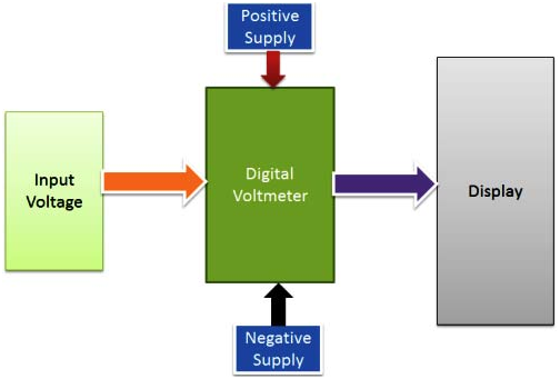
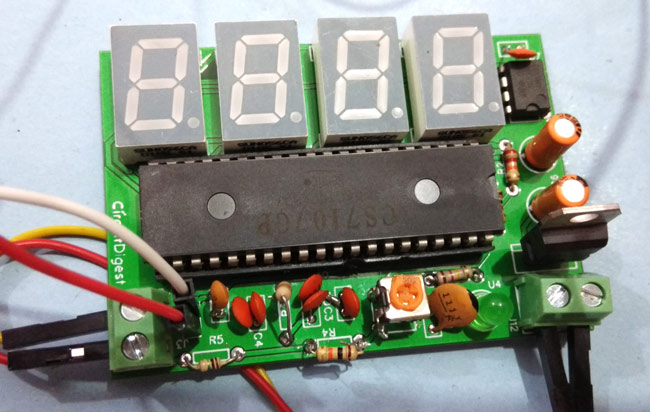
A voltmeter is a voltage measuring instrument. We can measure the potential difference between any two points in an electrical network using a voltmeter. Let us design and make a simple voltmeter using 8051 microcontrollers. There are two types of voltmeter as analog voltmeter and digital voltmeter. Analog voltmeter moves the pointer on a scale but it has some limitations like the accuracy of few percent of full scale.
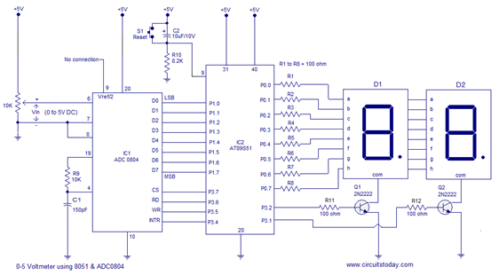
A simple 0-5V voltmeter using 8051.This digital voltmeter has a sensitivity of 200mV which is a bit low but this project is meant for demonstrating how an ADC and seven segment display can be interfaced to 8051 to obtain a digital readout of the input voltage. A 31/2 digit high end voltmeter will be added soon. ADC0804 is the ADC and AT89S51 is the controller used in this project.
A digital voltmeter can display the numerical value of the voltage on a display by use of analog to digital converter (ADC). All the data processing and manipulating are in digital form, so it is essential to use ADC. We have used ADC0804 analog-to-digital converter IC. The range of input voltage is 0-15V. Here the input voltage should be DC voltage so as to get the steady output on the LCD display. If you give the AC voltage as an input, it will display continuously running numbers as the nature of AC voltage.

About the circuit
In the circuit Vref/2 (pin9) of the ADC is left open and it means that the input voltage span can be o to 5V and the step size will be 5/255 = 19.6mV. The equation for the digital output of ADC0804 is Dout = Vin/Step size. In this circuit, for an input voltage of 1V the digital output will be 1/19.6mV = 51 and so the binary equivalent of 51 ie 00110011. Digital output of the ADC is interfaced to P1.0 of the microcontroller. Control signals for the ADC ie CS, RD, WR and INTR are available from the P3.7, P3.6, P3.5 and P3.4 pins of the microcontroller respectively. 2 digit multiplexed seven segment display is interfaced to Port0 of the microcontroller. Control signals for the display driver transistors Q1 and Q2 are obtained from P3.2 and P3.1 of the microcontroller. Push button switch S1, capacitor C2 and resistor R10 forms a debouncing reset circuitry.

Circuit Components
AT89C51 micro controller
ADC0804 IC
25V Voltage Sensor
AT89C51 programming board
Variable resistor (to demonstrate the program)
DC Adapter or Battery
Digital Voltmeter Circuit Design using 8051 Microcontroller
In the above circuit, analog to digital converter IC data bits are connected to the PORT2. LCD data pins are connected to the POTR3 of controller and control pins RS and EN are connected to the P1.6 and P1.7 respectively.
ADC0804
This is an 8 bit analog to digital converter. This IC uses successive approximation method to convert analog values to digital. It can take only one analog data as input. The step size of this IC is varied by varying the reference voltage at pin9. If this pin is not connected, VCC will be the reference voltage.
For every 19.53mV, rise in input voltage the output is incremented by 1 value when the step size is at 5V. The conversion time of this IC depends on clock source.
ADC Features
- 0 to 5V analog input voltage
- Built in clock generator
- Differential analog inputs
- Adjustable reference voltage
Below table shows the different step sizes for different reference voltages.
In the above circuit diagram, pin9 (Vref/2) is left open so that input voltage span can be 0 to 5V.
Voltage Sensor
The voltage sensor module is a simple voltage divider network that increases the analog input range of the ADC to about 25V.

Working of 8051 Microcontroller
Initially burn the program to the at89c51 microcontroller. Now give the connections as per the circuit diagram. Connect a battery or any voltage source at the input of the voltage sensor. Make sure that maximum analog input voltage should be less than 25V DC, Connect a digital multi meter at the Input terminals of the voltage sensor. Now switch on the board supply. Now observe both LCD and digital multi meter, both displays the same voltage (or very similar voltages). If possible, try to slowly vary the analog input voltage. Now you can observe that both multimeter and LCD displays the same voltages so that we can say that voltmeter is working properly. Switch off the board supply.
Digital Voltmeter Circuit Applications
- This system is used to measure the voltage in low voltage applications.
- Used to measure the toy batteries.
- We can measure the physical quantities like temperature, humidity, gas etc. using this system with a little modification.
Digital Voltmeter Circuit Limitations
- The input analog voltage range should be 0 to 5V.
- Using this system we can measure only one analog input value at a time.
Coding
#include <REGX51.H>
#include “lcd.h”
#define adc_port P1 //ADC Port
#define rd P3_7 //Read signal P3.7
#define wr P3_6 //Write signal P3.6
#define cs P3_5 //Chip Select P3.5
#define intr P3_4 //INTR signal P3.4
void conv(); //Start of conversion function
void read(); //Read ADC function
unsigned int adc_avg,adc;
void main(){
char i;
LCD_INI();
while(1){ //Forever loop
adc_avg = 0;
for(i=0;i<10;i++){
conv(); //Start conversion
read(); //Read ADC
adc_avg += adc;
}
adc_avg = adc_avg/10;
wrt_cmd(0x80);
wrt_string(“V(DC): “);
adc = adc_avg * 59;
hex2lcd((unsigned char)(adc/1000));
wrt_data(‘.’);
adc = adc%1000;
hex2lcd((unsigned char)(adc/10));
wrt_data(‘V’);
}
}
void conv(){
cs = 0; //Make CS low
wr = 0; //Make WR low
wr = 1; //Make WR high
cs = 1; //Make CS high
while(intr); //Wait for INTR to go low
}
void read(){
cs = 0; //Make CS low
rd = 0; //Make RD low
adc = adc_port; //Read ADC port
rd = 1; //Make RD high
cs = 1; //Make CS high
}


