Engineers are frequently faced with the challenge of developing applications to meet a wide range of requirements. Usually, these requirements are difficult to fulfill simultaneously. One example is finding a very fast, high voltage operational amplifier (op amp) with high output power and equally good characteristics in dc accuracy, noise, and distortion. Op amps combining all of these characteristics are rarely available on the market. However, it is possible to build such an amplifier yourself out of two individual amplifiers, creating a composite amplifier. When combining two op amps, the positive characteristics of each one can be incorporated. In this way, a higher bandwidth can be achieved compared to that of a single amplifier at the same gain.
The Composite Amplifier
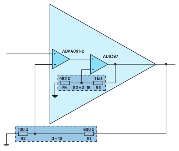
A composite amplifier consists of an arrangement of two individual amplifiers, often with different characteristics. Such an arrangement is shown in Figure 1. Amplifier 1 represents the low noise precision amplifier, ADA4091-2. Amplifier 2, in this case the AD8397, features a high output power that serves to drive additional modules.

The configuration of the composite amplifier shown in Figure 1 is similar to that of a noninverting amplifier in which the two resistors, R1 and R2, act externally. The two op amps connected in series should be considered a single amplifier. The total gain (G) is set via the resistance ratio, G = 1 + R1/R2. A change in the ratio of R3 to R4—and in effect, the gain of amplifier 2 (G2)—also affects the gain or output level of amplifier 1 (G1). The effective total gain is not changed by R3 and R4. If G2 decreases, G1 increases.
Bandwidth Extension
Another characteristic of a composite amplifier is a higher bandwidth. The bandwidth is higher for this combination than for each of the individual amplifiers. Thus, if two identical amplifiers are used with a gain-bandwidth product (GBWP) of 100 MHz and gain, G = 1, an approximately 27% higher, –3 dB bandwidth can be achieved. With increasing gain, this effect becomes even clearer, but only up to a certain limit. Once the limit is exceeded, instabilities may arise. This also applies in the case of uneven distribution of the two gains. In general, the maximum bandwidth is yielded with equal distribution of the gain over the two amplifiers. With the values mentioned above (GBWP = 100 MHz, G2 = 3.16, G = 10), a –3 dB bandwidth that is approximately 300% as high as that of a single amplifier can be achieved for a gain of 10.
The explanation is relatively simple. With an equally distributed gain, G2 also leads to the same effective gain of amplifier 1. However, the open-loop gain of each individual amplifier is much higher. With a lowered gain—for example, from 40 dB to 20 db—both amplifiers now act in a lower region of the open-loop curve (see Figure 2). Through this, a higher bandwidth is yielded with a composite amplifier than with a single amplifier at the same gain.

DC Accuracy and Noise
In a typical op amp circuit, part of the output is fed back to the inverting input. In this way, output errors can be corrected via the feedback path to improve accuracy. The combination shown in Figure 1 also offers a separate feedback path for amplifier 2, although it is in the feedback path of amplifier 1 . The output of the overall arrangement contains larger errors due to amplifier 2, but they will be corrected as they are fed back to amplifier 1. Thus, the accuracy of amplifier 1 is retained. The output offset is only proportional to the error of the first amplifier and remains independent of the offset of the second one.
The same applies to the noise component. It is also corrected via the feedback whereby ac signals are also dependent on the bandwidth reserve of the two amplifier stages. As long as the first amplifier stage has a sufficient bandwidth, it corrects the noise component of amplifier 2. Up to this point, its output voltage noise density is dominant. However, if the bandwidth of amplifier 1 is exceeded, the noise component of the second amplifier starts to dominate. Problems arise if the bandwidth of amplifier 1 is too high or much higher than that of amplifier 2. This can lead to an additional noise peak, which can be seen at the output of the composite amplifier.
Conclusion
Through a combination of two amplifiers connected in series, the best characteristics of both can be combined while achieving results that are unattainable with individual op amps. For example, a high precision amplifier with a high output power and a higher bandwidth can be achieved. Figure 1 shows an example of a circuit with the rail-to-rail amplifier, AD8397 (–3 dB bandwidth = 69 MHz), and the precision amplifier, ADA4091-2 (–3 dB bandwidth = 1.2 MHz), which in combination have a bandwidth that is more than twice as high as they each have individually (at G = 10). Furthermore, with the combination of the AD8397 and various precision amplifiers, noise reduction as well as THD improvements can be achieved. However, in the design, system stability must also be ensured through a correct amplifier configuration. If all criteria are considered, the composite amplifier offers numerous possibilities for covering a very wide and demanding range of applications.


