 The aviation and space industry has revolutionized the way humans travel, communicate and connect. Taking off from a 120ft 12 second flight, the avionics has matured since then in to a multiple day journey at 34000ft and beyond. The space race that blasted off the first satellite to space- Sputnik to show the solidarity and supremacy, has now evolved into an inevitablerealm with the satellites being launched to help the countries in communication, cartography, monitoring and positioning. Behind all these successful endeavors and rocket science, a prevalent yet overlooked system exists, which Powers these missions to success. In this article, let us introduce you the world of power supply- in aerospace and the recent technology and advancements in this area.
The power system of a spacecraft/aircraft is referred to as Electronics Power System (EPS). A general block diagram of EPS is shown in Figure 1.
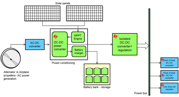
It has a primary source of power in the form of solar panels in satellites and the alternators that run in the propeller/engine in an aircraft. These generate the power for the whole machine- satellite or plane. The solar panel converts solar irradiation in to direct DC and the alternator passes generates alternating waveform (AC) and is passed through an AC-DC converter (rectifier).
This raw power can’t be directly made use of and hence a power conditioning unit is needed. It converts the raw power from the sources and into useful regulated supply and also stores itin batteries for back up.
The storage elements are composed of a series and parallel array of batteries; each cell with a voltage of 2-4V. These act as a back-up source of power or substitute the system when the power from the primary source is inadequate. Usually, when the sun is eclipsed from the solar panels due to other planets or bodies, the battery system powers the whole satellite.
The output stage in this system consists of an isolated DC-DC converter which ensures that the power requirement of the downstream load is met along with supporting transients and latch-ups. This stage usually powers a bus-called the satellite power bus that runs through the satellite delivering power to all the other control, communication and data subsystems. The bus typically is at 42V or 70V depending on the space agency and there is a plan to raise this voltage to 100V for an even efficient distribution. Further down the bus, at the point of load the higher current DC-DC converters and low drop-out regulators are used to power the load.
Let us investigate into the individual systems with a semiconductor device point of view and how Texas Instruments solutions simplify the solution with a differentiated approach.
Power conditioning subsystem
This unit is responsible for taking in raw power from the solar panels and the rectifiers and converting it in to useful energy. The typical block for a power conditioning block is as shown in figure 2 below.
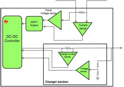
In space, the sole source of power is Sun and the solar panels help convert it into electricity. In order to ensure that maximum power is derived out of these panels at a given time, Maximum Power Point tracking (MPPT) algorithm runs in this system. Different algorithms and methods of implementation- analog or digital are used differing from satellite to satellite. In here, the variables for the MPPT algorithm are sensed using precision and high voltage op-amps. The different op-amp configurations help sense the panel voltage and current along with the power at the output of the internal DC-DC switcher. These feed into the MPPT algorithm thereby enabling the maximum power extraction from the panels. Texas Instruments offers a widerange of amplifiers that cater to the different need of the power systems- high common mode voltage, low offset and temperature drift, multi-channel configuration and optimal bandwidth (1-5MHz). A few satellites may not implement the MPPT and thus have just the PWM controllers to generate the power at the output. This unit sometimes also co-ordinates with the satellite orientation control system to adjust the solar panels to face the Sun directly so as to maximize the power generated.
This unit also constitutes a battery charger section that helps for a controlled charging of the batteries. To charge the battery, monitoring the rise in battery voltage and the charging current is necessary to take corrective action. A high common mode input current sense amplifier is needed here along with a low offset voltage op-amp. Texas Instruments’ wide input voltage current sense amplifier- INA203 with built-in dual comparators and voltage reference helps achieve this purpose. Also, OPA4277-SP quad op-amp with very low offset voltage of <140uV can help achieve accurate measurements. As legacy solution, LM124QML-SP has been used to achieve this purpose.
Storage section- Batteries
Inside the battery section, a large stack of individual cells add up to give the required voltage and power. However, individual cell needs to be monitored for voltage and balanced for power. Here TI’s lowest offset voltage op-amp, dual channel; LMP2012QML-SP is typically used to monitor individual battery voltages. With sub mA supply current, it makes one of the best solutions to work with battery powered sources. Also, the quad OPA4277-SP can be made use to sense 4 stacks at a time.
Isolated DC-DC converter
A typical block diagram of the DC-DC converter looks as in figure 3.
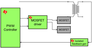
Here, the main emphasis is to convert the stored energy from battery or power conditioning block into a regulated bus supply. Different topologies like flyback, forward with active clamp, push pull and phase shifted full bridge are used depending on the power requirement(from smallest to highest). The typical output voltage is around 42V or 70V. Texas Instruments provides a range of flexible solution in this area by offering PWM controllers, MOSFET drivers and isolated feedback generators. Some of the hero parts having a long space heritage are UC1875-SP (Phase shifted full bridge) controller, UC1825-SP (Push-pull PWM) controller, UC1901-SP (isolated feedback generator) and UC1715-SP (complementary MOSFET driver). To supplement this, TI also offers fixed and adjustable voltage references with 0.1% accuracy and <20ppm temperature co-efficient: LM4050QML-SP and TL1431-SP. Many of these controllers and drivers are available in die form and are made used to make Hybrid Micro Circuits(HMC)
DC-DC point of load converter
Historically, the processors and FPGAs consumed less power and could be powered directly off a linear regulator. With the rising demand for on-board processing, the capabilities and hence the power consumption of the FPGAs have risen. The power supply has to shift from an inefficient linear regulator to a switching buck converter to support these high currents. The typical power tree for modern FPGA is shown in figure 4.
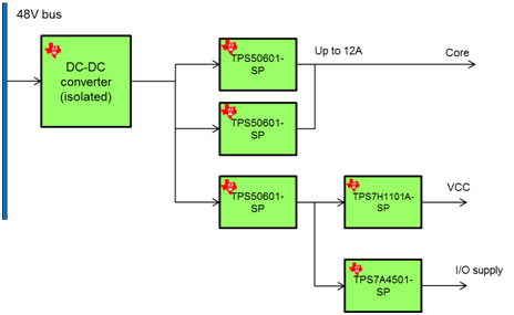
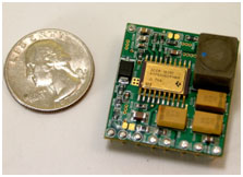
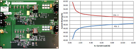
Texas Instruments offers industry’s most compact rad hard 6A DC-DC switcher with integrated MOSFETs with output voltage settable from 0.9V to 3.3V- TPS50601-SP. It has a peak efficiency of 95% at 3.3V output and a 1.2 x 1.3 inch solution area. The adjustable switching frequency helps meet the required efficiency and reduce thermal dissipation. To cater to higher current requirements, two of these devices can be connected with a common output voltage to source up to 12A. The size of the solution compared against a quarter is shown in figure 5.
The dual configuration is shown in figure 6 below along with the accuracy of current sharing. With output current beyond 6A, the sharing is as accurate as ±2%
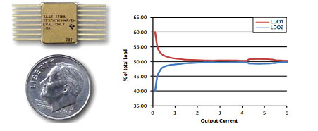
TI also has a comprehensive array of linear regulators catering to different input voltage and current conditions. Starting with LM117HQML which can accept up to 60V input voltage and source 1.5A, it offers a 3A LDO with one of the best drop-out voltage of <300mV across temperature- TPS7H1101-SP. It also caters to mid-voltage(up to 20V input) LDO with a 0.75A and 1.5A variant- TPS7A4501-SP. Two TPS7H1101A-SP can be connected with a common output to share current and source up to 6A.
With the increase in the processing power and speed of the digital section, the need for DDR RAM memory has gone up. In order to support the termination requirement of these RAM, TI has introduced a linear DDR terminator with 3A current capability. It has a built-in reference voltage buffer that eliminates the need for an external buffer. It also supports DDR4 RAM termination thus emphasizing TI’s vision on the future of space technology.
With the aforementioned strong rad hard portfolio and roadmap for higher current and wider Vin DC-DC converters and low drop-out regulators, TI stands clear in its focus and emerges as a reliable leader in space POL power. For more details, please visit Texas Instruments website: www.ti.com/space and the below reference designs
- Mini POL design: http://www.ti.com/tool/PMP8904
- TPS7A4501-SP powering ADS1282: http://www.ti.com/tool/ads1282evm-cval
- DDR Termination design board: http://www.ti.com/tool/tps7h3301evm-cval


