What is Isolation?
Isolation is a means of transporting data & power between a high voltage and a low voltage circuit while preventing hazardous DC or uncontrolled transient current from flowing in between the two.
Why do we need Isolation?
Isolation is required in modern electrical systems for a variety of reasons. Some examples are to protect from and safely withstand high voltage surges that would damage equipment or harm humans. For example Medical Equipment’s like ECG, Patient Monitoring System, etc. where the leads are put in contact with the human body; any uncontrolled transient current from the AC side (High Power) flowing to the other side (low power DC) can become lethal for the patient. Similarly, we need Isolation to tolerate large ground potential differences and disruptive ground loops in circuits that have high energy or are separated by large distance, example Programmable Logic Controller system, where physical separation of the field sensors from the PLC creates ground potential differences that can cause reverse flow of current in the ground loop. Lastly, to communicate reliably with high side components in high-voltage motor/inverter drive systems, switches, etc.
Where to Isolate?
In most applications, Isolation separates the “Real World” from sensitive controllers, may it be Microcontrollers, Programmable Logic Controllers, or Digital Signal Processors.
In an Industrial system, wherever there is a data bus that is operating in harsh, noisy conditions, it is advisable to introduce an isolator in between the bus and the processor to prevent the noise from the bus to be transmitted to the DSP.
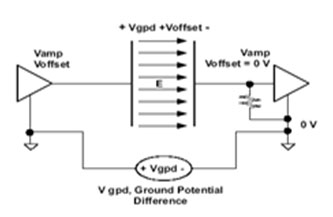
Ground loops are the most common source of noise in acquisition applications. They occur when two connected terminals in a circuit are at different ground potentials, which causes current to flow between the two points. So we need to introduce Isolators to breaks these ground loops.
Isolation uses the physical and electrical barriers to provide safety benefits by keeping high voltages or high transient voltages away from the user or away from important circuit components, which we will discuss in later sections.
Isolation Technologies:
Over the years, we have seen designers using different Isolation techniques to transmit the signal data over the isolation barrier. Physical isolation is the most basic form of isolation, meaning that there is a physical barrier between two electrical systems. This can be in the form of insulation, an air gap, or any nonconductive path between two electrical systems. With pure physical isolation, you can imply that no signal transfer exists between electrical systems. Three common techniques of transferring the signal across the isolation are discussed below
1. Optical Isolation
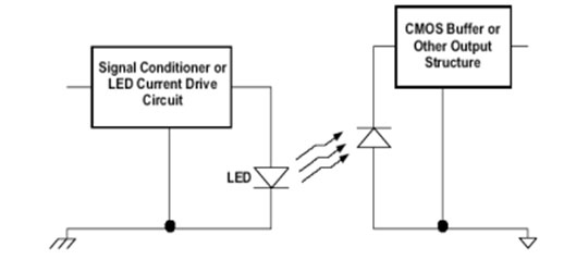
Optical isolation uses an LED and a photodetector to transmit the signal information across the isolation barrier. The isolation barrier in optical isolation is typically an air gap and the signal is transmitted using light. The light intensity produced by the LED is proportional to the measured signal. In Ideal Scenarios, an Optical Isolation is immune to both electric and magnetic field interference but in actual scenarios, we do see failure of optocouplers at high stress across the barrier. When it comes to low power dissipation and small form factor, Optical Isolation has its own limitations.

2. Inductive Isolation
Inductive isolation uses a transformer, shown in Figure below, to transfer a signal across an isolation barrier. The signal is transferred from one side to another through magnetic/ inductive coupling.
Traditionally, Inductiveisolation can provide low-speed data transmission rates at lowpower but at higher data rates the power dissipation is much higher. In Industrial applications where radiated emissions and radiated immunity is important, Inductive isolation is not the best choice. Inductive coupling is susceptible to very strong magnetic fields because it uses magnetic coupling.
3. Capacitive Isolation
Capacitive isolation, as seen in Figure below, uses capacitive coupling to transfer signal across the isolation barrier.

Capacitive Isolators have very low power dissipation even at higher data transmission rates compared to Optocouplers. Another advantage with Capacitive Isolation is lower EM radiations, susceptibility.
In Capacitive Isolation, immunity to surrounding electric fields is achieved through differential operation. Let us see the operating principle and the different architectures used to achieve it
In general, an isolator can be abstracted as comprising of a high voltage isolation component or barrier, a transmitter (TX) to couple signal into one side of the isolation component, and a receiver (RX) to convert the signal available on the other side of the isolation component into digital levels.
TI’s isolators use SiO2 (silicon dioxide) based, high-voltage capacitors to serve as the isolation component.For the TX and RX circuits, two different architectures are used: Edge based and On-Off Keying (OOK)based. These architectures are explained below –
1. Edge-Based Communication
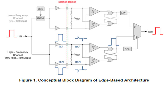
The conceptual block diagram of edge-based communication is shown in Figure 1. The isolators of TI’s ISO73xx, ISO74xx, ISO71xx, ISO76xx, ISO75xx, and ISO72xx family of devices use this architecture in some form.
The device consists of at least two data channels, a high-frequency channel (HF) with a bandwidth from 100kbps up to 150Mbps, and a low-frequency channel (LF) covering the range from 100kbps down to dc.
In principle, a single-ended input signal entering the HF-channel is split into a differential signal via the inverter gate at the input. The following capacitor-resistor networks differentiate the signal into small and narrow transients, which then are converted into rail-to-rail differential pulses by two comparators. The comparator outputs drive a NOR-gate flip-flop whose output feeds an output multiplexer. A decision logic (DCL) at the driving output of the flip-flop measures the durations between signal transients. If the duration between two consecutive transients exceeds a certain time limit (as in the case of a low-frequency signal) the DCL forces the output-multiplexer to switch from the high-frequency to the low-frequency channel.
Because low-frequency input signals require the internal capacitors to assume prohibitively large values, these signals are pulse-width modulated (PWM) with the carrier frequency of an internal oscillator, thus creating a sufficiently high frequency, capable of passing the capacitive barrier. As the input is modulated, a low-pass filter (LPF) is needed to remove the high-frequency carrier from the actual data before passing it on to the output multiplexer.

 2. On-Off Keying (OOK) Based Communication
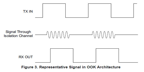
The conceptual operation of OOK-based communication is shown in Figure 2. The corresponding signaling is shown in Figure 3. The isolators in the TI’s ISO78xx family of devices use this architecture.
In this architecture, the incoming digital bit stream is modulated with an internal spread spectrum oscillator clock to generate OOK signaling, such that one of the input states is represented by transmission of a carrier frequency, and the other state by no transmission. This modulated signal is coupled to the isolation barrier and appears in an attenuated form on the receive side. The receive path consists of a pre-amplifier to gain up the incoming signal followed by an envelope detector that serves as a demodulator to regenerate the original digital pattern. The TX and RX signal conditioning circuits are used to improve the common mode rejection of the channel resulting in better Common Mode Transient Immunity (CMTI).
Conclusion
Although Optocouplers have been a traditional way of providing Isolation for many years, but with Industry’s move to the next generation Industrial Automation and Control (Reliable links between Controllers/Sensors/Actuators) there is a need for superior protection, immunity and features with low cost, compact packages and high efficiency. Optocouplers have been a low cost option for a long time but in a typical Industrial application, where small form factor and low power dissipation are the key care abouts, the usage of Capacitive & other Isolation techniques is expanding and becoming popular
Author


