| AUTHORS Jin Xu, Applications Engineer, Automotive Products GroupKakul Chaudhry, Applications Engineer, Automotive Products GroupPriyabrata Sinha, Principal Applications Engineer, Digital Signal Controller DivisionJorge Zambada, Applications Engineer, Digital Signal Controller Division Microchip Technology Inc. |
In the continuing proliferation of electronic control modules within the vehicle of tomorrow, Silicon is only part of the story. Development tools are a significant element in the plan of transforming ideas into realities. The typical product development life cycle is continuously challenged to become shorter. With constant pressures to get products to market faster and within the development budget, development tools—including hardware, software and reference designs—are essential for supporting automotive embedded designers as they move a project from conceptual design through coding, debugging, and programming.
| I |
ntegrated tool sets, in-circuit emulators, advanced solution software libraries and targeted application reference designs help automotive embedded designers focus on important details and correlate information throughout the entire development process from the design phase through the debugging, optimization and programming phases. With increasing constraints on design cost and time, there has been an influx of enhanced development tools and resources available to designers for increased productivity. These include, but are not restricted to, the Integrated Development Environment (IDE) tools that include hardware and software support and reference designs developed the by the semiconductor manufacturers and other third-party vendors.
Comprehensive IDEs Boost Productivity In Design and Development
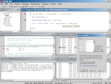
An IDE is an all encompassing development environment/tool where the designers create, develop, test and implement their embedded application. IDEs are comprised of software and hardware tools which can be accessed through a Graphical User Interface [(GUI), see Figure1].
A well-designed and comprehensive IDE helps reduce the learning curve of using a new device by making it easier to interface with the device in order to program it via quick debugging tools. This gives the user more time to focus on their specific application needs.
Figure 1: An IDE Features A Text Editor and Several Debugging Menus
From inception to release, the code goes through a cycle, as shown in Figure 2: 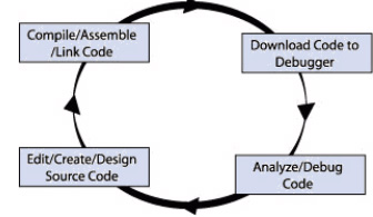
Figure 2: Code-Development Cycle
In this process, multiple tools are needed—an editor to write the code, a project manager to organize files and settings; a compiler or assembler to convert the source code to machine code; and some sort of hardware or software that either connects to a target microcontroller, or simulates the operation of a microcontroller. The faster the automotive embedded designer can traverse this loop, the quicker the application will be completed and ready to ship. This loop will be followed many times, for typos found in writing code when bugs arise in the implementation, as optimizations are realized, and as the performance of the application is adjusted
An IDE such as the MPLAB® IDE from Microchip allows the designer to move quickly between these various phases of development, resulting in a shorter time to market for the application.
Editor
An IDE text editor allows designers to write and edit source code. A smart editor is aware of programming constructs. It parses the code as you type and immediately marks errors. Smart code completion makes suggestions and provides hints. This allows the user to spend less time searching for the correct syntaxes and fixing errors upon compiling the code.
Project Manager
The project manager allows designers to create and associate source files with the compilers, assemblers, librarians, and linkers to build their final application. Designers can even include non-code files, such as PDF files and other file types, which provide quick and easy access to datasheets and other files related to the project.
Debugging
Using IDE tools such as the MPLAB IDE, designers have multiple options to debug their code based on their device and application needs.
Built into the IDE is debugging software which simulates the functionality of a microcontroller. Therefore, it allows the user to test an application code without programming the actual device. The debugger uses the PC to simulate microcontroller instructions and many peripheral functions, such as analog-to-digital conversion, USARTs and pin I/Os. Stimulus signals can be injected into registers or onto pins, without the use of any additional hardware, and it can also create a log to register changes that can be saved in a text file for further analysis.
Simulators can help save development time, as designers can start the code development even before the actual hardware for testing it is available. Testing the code on the simulator can also prevent hardware damage in case of errors in the code.
When the actual device is programmed to be tested, it may interact unexpectedly with the external components. In order to debug the device in a real-world application, the IDE uses hardware tools to interact with the device’s circuitry to debug the code. These tools work in conjunction with the IDE’s graphical interface features, to allow for easier interaction and implement complex debugging techniques such as placing hardware or software breakpoints in the code, tracing code execution, monitoring changes in data values, etc.
Role of the IDE in Networked Vehicles
The growing number of Electronic Control Modules (ECMs) within the vehicle creates an environment for the “networked” vehicle. Advancing ECMs are essential, in order for car manufacturers to produce smarter vehicles that are pleasing to drive, and are more reliable, and safer. Networks are a key element of the vehicle’s electrical architecture. Figure 3 shows the various communication networks utilized within the vehicle, along with the relative cost to implement a node for each. Two of the most popular automotive networks are the Controller Area Network (CAN) and Local Interconnect Network (LIN).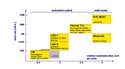
Figure 3: Automotive Networking Protocols
In the continuing effort to find ways to make embedded designers more productive, the following examples illustrate how an IDE can be a productivity-enhancing tool.
LIN Communication Protocol
The LIN protocol is a holistic communication concept for smaller vehicle networks. The specification covers the definition of the protocol and the physical layer, as well as the definition of interfaces for development tools and application software. LIN enables a cost-effective communication network for vehicle switches, smart sensor and actuator applications where the bandwidth and versatility of CAN is not required. This communication protocol is based on the SCI (UART) data format, with a single-master/multiple-slave concept, with a single-wire 12V bus, and clock synchronization for nodes without a stabilized time base.
The protocol hardware cost is low, due to simple hardware requirements. But the Tier 1/Tier 2 supplier incurs significant development cost, as most of the protocol implementation is done in software. To gain a good understanding of the protocol to develop the software requires learning new communication concepts and can be time consuming. The software tends to be very complex and usually results in an extended, intensive debug process.
In order to reduce the development and debug time, automotive embedded designers can use certain tools, like the LIN Driver Configuration Tool (see Figure 4) from Microchip, to make the process more efficient. This tool was developed by iHR GmbH in partnership with Microchip. This tool helps automate the process of generating LIN-compliant driver code using a simple LIN Description File (LDF) text file, which contains the bus configuration information, node information and signal data. Thus, automotive embedded designers do not need to spend any time trying to understand the LIN protocol and how to encode, and decode, the messages. The tool’s GUI enables designers to specify application-specific bus characteristics and extract the information from the LDF file. The GUI also generates the code tailored for the application. The designer can then access the LIN driver with simple API calls and focus their efforts and time on developing the core application software, rather than spending time just developing the communication segment of the code. 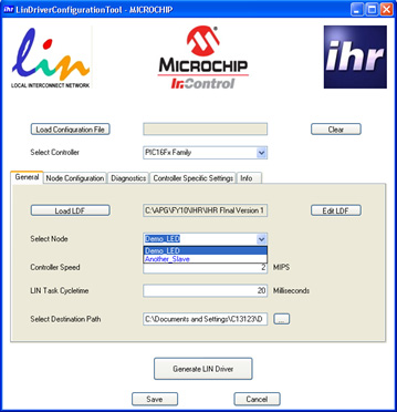
Figure 4: LIN Driver Configuration Tool GUI
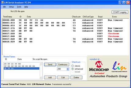
Microchip has also developed a LIN Serial Analyzer tool (see Figure 5), which has several features which make the task of debugging and developing the LIN bus faster, and easier. 
Figure 5: LIN Serial Analyzer Tool from Microchip Technology
Microchip’s LIN Serial Analyzer tool comes with a user-friendly GUI that runs on the PC and allows the user to send and receive messages on the bus (see Figure 6). The tool monitors the bus for messages, and then decodes and displays them in a simplified and understandable format on the GUI. What this means is that the user does not need to spend any time trying to capture the signals on an oscilloscope, and then go through the tedious process of decoding it, based upon protocol rules. The tool detects and identifies if there were any errors on the bus, saving the designer time, which can now be spent trying to identify the cause of the error. The tool also calculates the bus speed, saving additional time.
The tool also allows the user to be able to send LIN-compliant messages on the bus to test whether the code on the controller is interpreting them correctly.
Figure 6: LIN Serial Analyzer Tool GUI
CAN Communication Protocol
The CAN protocol offers a multi-master hierarchy that supports the development of intelligent, redundant systems. In this type of network, if a network node is defective, the network remains functional. Messages are broadcast across the network. All nodes receive the messages, and are able to read the message and determine whether they are relevant to them, and/or require any action. In this environment, data integrity is ensured—as all nodes of the system use the same information. Data integrity is supported via error-detecting mechanisms and retransmission of faulty messages.
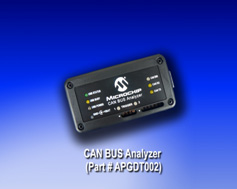
The CAN Bus Analyzer tool (see Figure 7) is a simple to use CAN bus monitor which can be used to design and debug a high speed CAN network with an intuitive and easy to use graphical user interface. The tool allows designers to view and log received and transmitted messages from the CAN BUS. Designers are also able to transmit single or multiple CAN messages onto a CAN BUS, which is useful during development or testing of a CAN network.
Figure 7: Microchip’s CAN Bus Analyzer Tool
Using this CAN BUS Analyzer tool has many advantages over the traditional debugging methods embedded engineers typically rely upon. For example, the tool trace window will show the user the received and transmitting CAN messages in an easy to read format (e.g. ID, DLC, data bytes and time stamp). In traditional debugging, the designer would have to convert the register hexadecimal values of a received ID into usable form.
Importance of Reference Designs
Reference designs help reduce development time and costs. Reference designs are good starting points for a project during the early stages of its launch. In most cases, the reference designs, themselves, are for reference, only. They are not intended to be production ready. In today’s the competitive markets, the scope of references designs in some cases are expanded in a movement toward “production worthiness” as suppliers strive to be responsive to the automotive embedded designer’s request for development tools to assist in their quest to get their designs to market faster at the lowest feasible cost.
Using IDE tools, designers can further optimize a reference design to address the specific requirements of their application module, whether it is in a window-lift application, a keyless-entry application or Brushless DC (BLDC) motor control in a fuel-pump application. Reference designs not only assist designers in reducing their development time, but also can be an effective source of new ideas in addressing application requirements. With this in mind, let us look at a few automotive reference designs.
Motor-Control Applications
One of the most extensively-implemented embedded designs in a vehicle is a motor-control module. From seat controls, to HVAC controls, to fuel-pump controls, to power-steering controls, a wide range of motor types, including BLDC, sensorless BLDC, Brushed DC (BDC) and Permanent Magnet Synchronous Motors (PMSMs) are being implemented to solve application requirements. Barring any application-specific requirements, the basic motor-control algorithms for each of the motors is very similar. So, the automotive embedded designer can use existing motor-control reference designs consisting of application notes, firmware, schematics, Gerber files, assembly diagrams including bill of materials (BOM) to significantly reduce their research and design time.
For example, brushed motors are still a popular choice in the vehicle because of their low cost, controllability and ease of use. If an embedded designer is tasked with developing a motor-control module for any application, such as the window lift with anti-pinch functionality, seat controls, sun roof controls, or sliding door controls, their first choice of motor would be a brushed DC motor. To aid in the design and development of any these applications, designers may consider using a reference design, such as Microchip’s Anti-Pinch Window Lift Reference Design.
The reference design comprises of a small MCU, voltage regulator, relays and drivers, input conditioning circuitry and network physical-layer interface. The signal-conditioning circuitry usually features an H-Bridge controller and a 10-bit Analog-to-Digital Converter (ADC). Bi-directional motor control with active feedback for implementing anti-pinch functionality is typically provided by the coupling of H-Bridge controller with ADC. An integrated LIN protocol module enables intersystem communication within the door module, as well as the main body controller.
PMSM Control Reference Designs
Due to safety and reliability issues, the latest cars are moving toward deploying PMSMs in their rotating subsystems. Besides requiring complex drive circuitry, PMSMs require DSC-based control algorithms, such as Field Oriented Control (FOC), for delivering optimum performance. These advanced motor-control schemes can readily be developed using existing reference designs. They can be configured and debugged using IDE tools. For example, the MPLAB IDE offers a Data Monitor and Control Interface (DMCI) that integrates with an IDE for projects in which the operational constraints of the motor control can be understood graphically.
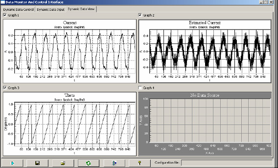
DMCI tools (see Figure 8) allow designers to graphically adjust and plot software variables in motor-control applications. They typically provide slider controls, Boolean (on/off) controls, input controls and graphs (see Figure 9). The interface provides project-aware navigation of program symbols (variables) that can be dynamically assigned to any combination of slider, direct input or Boolean controls. The graphs can be dynamically configured for viewing program-generated data.
A DMCI’s motor control graphical user interface typically enables users to configure the motor and a wide range of system parameters for a selected motor type. These should include speed, rotation direction, current, heat sink temperature and fault status. These tools usually support the vendor’s motor control demo boards that help reduce design time. These tools, which run under an IDE, are useful for tweaking software parameters and visualizing historical data during debug sessions. 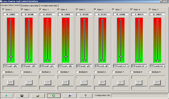
Figure 8: Slider Controls and Boolean Status Buttons
Help Tweak Variables in DMCIs
A major advantage to deploying IDE-based tools in automotive motor-control applications is the practicality of a common design platform, which makes the production of ECMs more efficient. This means automotive module makers now have an economical way to offer a range of modules that use PMSM or other motor types to employ with sensorless FOC algorithm control. DMCI tools make fine tuning motor control easy, allowing designers to port their algorithms across a variety of motor platforms, including PMSM, BLDC, BDC and AC-Induction (ACI) motors.
Figure 9: Motor Currents and the Commutation Angle During
FOC Control for PMSMs
Conclusion
Automotive embedded designers can expect changes in car-OEM requirements and environmental standards that are expected to advance the utilization of ECMs in vehicles. For example, the need for advanced motor-control techniques for creating energy-efficient modules to be deployed within the vehicle are expected to expand. The dependence upon motor-control solutions from proprietary sources will lessen as suppliers of microcontrollers and Digital Signal Controllers enable the implementation of advanced, cost-effective motor-control algorithms. This flexibility will allow automotive Tier 1 and Tier 2 suppliers to be more responsive to the increasing demands of car OEMs and their ultimate customer, the driver of the vehicle.
Effective utilization of various IDEs will allow designers to further optimize reference designs so that they are able to implement specific auto-related functions in accordance with the defined module requirements. With a consistent user interface for multiple hardware and software components, IDEs enable designers to rapidly develop and debug automotive subsystems. These tools enhance designer productivity by allowing an individual or a team of designers to work on projects—correlating information throughout the entire development process from design to debugging, and through the optimization, and programming phases.


