Single- and three-phase inverters in solar, UPS or energy storage applications today demand for high efficiency, compact designs and extended reliability. Inverter implementation in these applications is limited by silicon devices’ high dynamic losses when operated at 1200V. Alternative designs using 600V/650V devices can partially improve efficiency. However, they come at the expense of more complex topologies with special control schemes and high component count.
A Silicon Carbide (SiC) Schottky diode has no real reverse recovery charge. Thus a hybrid set of 1200V SiC diode and 1200VSilicon (Si) IGBT enables simpler 2-level topologies by reducing the diode turn-off loss as well as dramatically lowering the turn-on lossof the Si IGBT.
In this setup the static losses of the SiC diode often limit the optimization potential of Si IGBT/SiC diode solutions. To overcome this limitation, the new Generation 5 diode from Infineon comes with a reduction of forward voltage and its temperature dependency to reduce static losses. This article describes how consistent innovations in device design and assembly techniques improvediode performance, reliability and cost position resulting in easier system implementation forefficient, reliable and robust inverter designs.
Zero reverse recovery charge – the signature of SiC Schottky diodes
Silicon pin diodes are bipolar devices depending on the injection of minority charge carrier which are characterized by a large reverse recovery charge. During conduction state of the diode, charge carriers are injected into the device and need to be removed from the device before a voltage can be blocked or, in other words, a space-charge region can be built-up. A higher charge carrier concentration will result in a high reverse recovery charge. Moreover, reverse recovery charge is dependent on forward current and device junction temperature. The advantage of using SiC Schottky diodes being a majority carrier device is that they virtually show zero reverse recovery charge. Looking at the switching waveforms in Figure 1,the reverse recovery current peak is very small compared to a fast Si pin diode. Only the displacement current from the junction capacitance is visible. This leads to significantly lower turn-off losses. Moreover, since the dynamic characteristic of a Schottky diode is capacitive in nature, the reverse recovery characteristic of a SiC Schottky diode is independent from forward current, di/dt and device junction temperature.

Static loss reduction and improved thermal performance
The new1200VSiC Schottky diodes implement a merged pn-Schottky (MPS) structure, representing the same technology base as the latest 650V diode generation. To better understand this MPS design, the anode side of a SiC Schottky diode is shown in Figure 2. The blocking capability of a SiC diode during reverse voltage application is provided by a drift layer. This layer is also a major contributor to the overall resistance of the device. In this regard, it is best to lower the drift resistance to lower the forward voltage when the diode is conducting. A higher drift layer doping (n) lowers the resistance but at the expense of higher device leakage current.
Introducing p+ islands in this structure additionally shields the electric field from the Schottky contact thus reducing the leakage currents. Hence, using MPS structure enables lower overall resistance by increasing drift layer doping without significantly increasing the leakage current.

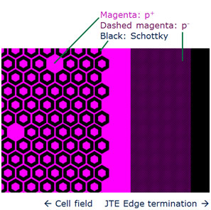
Figure 2: 1200 V thinQ!™ SiC Schottky diode Generation 5 design. MPS (merged-pin-Schottky) structure combines the shielding of the electric field from the Schottky barrier and an increased surge current capability by hole injection. (a)Dashed lines show current density at higher currents. (b)Cell design of an optimized cell structure with hexagonal p+ islands.
The new structure of the Generation 5 diodes leads to a 50 percent reduction of drift resistance compared to the previous Generation 2, which is a pure Schottky design. In Figure 3, the forward voltage contributions at 600A/cm2 are shown for the new and previous diode generation. Current densities are usually lower and mainly depend on the achievable thermal resistance Rth of the packaging vehicle. Even more significant is the mild increase in forward voltage during application operation at full load condition. This improvement can now be used for higher current density design with reduced static losses.

Massively increased surge current handling
Another positive side effect of the MPS design is the increased surge current capability. At higher currents the build-in voltage of the p+ islands in n-junction is overcome and holes are injected into the drift layer. The diode becomes bipolar in terms of forward characteristics, as shown in Figure 4. Due to this design, Infineon’s generation 5 1200V SiC Schottky diode is able to withstand surge current levels more than 15 times the nominal current for a typical 10 ms sine half-wave.

Thin wafer technology for lower forward voltage and improved thermal performance
To provide mechanical stability to the semiconductor device, a substrate is used which is depicted in Figure 5a schematic cross section of a SiC Schottky diode. The substrate resistivity labeled as Rbulk is also a significant contributor to the diode’s total differential resistance. The thickness of this substrate has a direct impact on the forward voltage when the diode is conducting. It is therefore best to reduce this thickness to lower the forward voltage while considering mechanical stability.
The well-established thin wafer technology allows for the reduction of the substrate thickness to around one third compared to the originallay out. With this thickness, the reduced total differential resistance leads to a 150 mV to 200 mV reduction of typical forward voltage for the identical chip sizes.
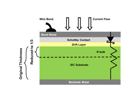
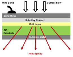
Figure 5: Schematic representation of a SiC Schottky diode indicating thick and thin wafers (a) and showing the thermal path for the heat generated in the junction of the diode (b). Merged pn junction is not represented for simplicity.
Besides the reduction of the forward voltage, the reduced chip thickness also leads to an improved thermal resistance which, in return, is beneficial for the power dissipation of the device. Obviously, a thinner substrate layer offers a shorter thermal path for the heat generated inside the Schottky junction and drift layer of the diode. The heat spread from the junction is enhanced, thus reducing the thermal resistance between junction and the package lead-frame or case. This holds true especially if sophisticated low Rth die attach techniques like diffusion soldering are used. In addition, the thin substrate enhances the propagation of the thermal flux not just only vertically but also laterally as shown in Figure 5b. The reduction in thermal resistance thus corresponds to an equivalent increase of power dissipation for the same case temperature. However, it has to be kept in mind that by wafer thinning the “junction-near” thermal capacitance (Cth) is reduced. Regarding short-time events like surge current there is a trade-off between the reduction of forward voltage drop and the reduction of Cth.
Experimental results in a boost topology
The performance of SiC and Si diodes was evaluated in a boost circuit. The test setup has an input voltage of 400 VDC and an output of 800 VDC capable of delivering 3000 W output power. IKW25N120H3, a 25A 1200V IGBT from Infineon is used as a boost switch switching at 20kHz.A commercially available 18 A ultrafast Si diode commonly integrated for this output power range was used. The boost inductor has an inductance value of 2.5mH.Figure 6 plots the efficiency curves and boost diode case temperature as a function of the output power for a 10A SiC and 18A Si diodes used as boost diode. The tests were performed at an ambient temperature of 25°C.

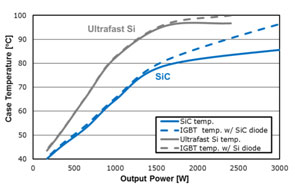
Figure 6: (a) Efficiency results of boost circuit and (b) boost diode case temperature of the 10A SiC and 18A Si diode over a maximum output power of 3000W.
At 2400W output power, the boost efficiency using SiC is 97.9percent compared to Si diodes’ 97.0percent. The measured case temperature at this output power for the Si diode is 96.7°C while the SiC diode reaches 84°C.Due to reduced reverse recovery charge of SiC, the boost output power can reach 3000W at a case temperature of 85°C.
To compare the efficiency improvement of the SiC diode technology generations, the same test setup mentioned above is used, except for the boost switch. In this test a SiC JFET is used as the boost switch, which enables a maximum output power of 6kW.Figure 7plots the efficiency curves and boost diode case temperature as a function of the output power percentage.
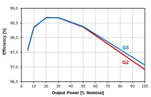
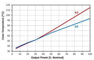
Figure 7: Efficiency (a) and SiC diode case temperature (b) results of a boost circuit with 800V output voltage, with Infineon’s generation 5and generation 210A SiC Schottky diodes in TO-247.
At 100 percent output power, boost efficiency using Generation5is 97.1percent while Generation 2 achieves 96.2percent. Moreover, at this output power the measured case temperature for Generation 5 is 93.6 °C while Generation 2 is 115.1°C. This reduction of device temperature at 100percent output power is the result of the diodes’ loss reduction which amounts to 30percent.
Summary
Compared to a pure Si based solution design engineers gain a higher flexibility in system optimization for UPS, solar inverters, energy storage and other industrial applications when using hybrid Si IGBT/SiC diode sets. The replacement ofa Si by a SiC diode increases the system reliability because of lower device temperatures. Additionally, a higher output power in the same form factor can be achieved. By minor additional system changes, power density can be increased even when using smaller heatsinks and EMI filters. The new Generation 5 1200V SiC Schottky diode from Infineon supports this higher flexibility with a low-loss turn-off, a dramatic improvement in static losses especially at elevated temperature and a massively increased surge current capability.
References
[1] Björk, F., Harmon, O., Draghici, M., Gerlach, R., Basler, T., Rupp, R. (2015). “1200 V thinQ!™ SiC Schottky Diode Generation 5: what are the three keys for simple, compact and high efficiency inverter designs?” PCIM Europe 2015.
[2] Fichtner, S., Lutz, J., Basler, T., Rupp, R., Gerlach R. (2014). “Electro – Thermal Simulations and Experimental Results on the Surge Current Capability of 1200 V SiC MPS Diodes” proceedings of CIPS, 2014.
[3] Rupp, R., Gerlach R., Kirchner U., Schlögl A., Ronny Kern R., “Performance of a 650V SiC diode with reduced chip thickness”, ICSCRM2011, proceedings of.
[4] Scarpa, V., Kirchner, U., Gerlach, R., Kern, R. (2012). “New SiC Thin-Wafer Technology Paving the Way of Schottky Diodes with Improved Performance and Reliability,” PCIM Europe 2012.


