The 555 is one of the most popular chips on the market and hundreds of projects have been created using it.


More than 30 billion have been produced and it can do almost anything.
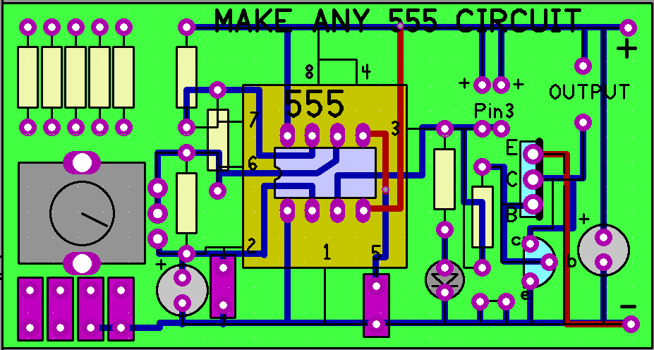
This project is a universal 555 board with components laid out in the same locations as on a circuit diagram, to make it easy to produce a project.
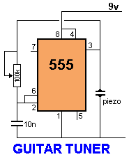
The components are not labelled so you can use your own values. Here are two circuits that can be created on the board. The description for these circuits is on the web.
One of the difficulties in making a project is to convert a circuit into a layout on a PC board and this board overcomes the problem.
This is because the components are placed in the same locations on the board, as on the circuit diagram.
The 555 chip has been drawn on the board with the components placed around it.

All you have to do is fit the components (and the chip in an IC socket) and connect the supply.
Some of the parts have to be connected under the board with tinned copper wire but this is much easier than using a matrix board or breadboard and you get a completed
circuit, ready for connecting to a project, that looks like the REAL THING.
The board will not suit all circuits, but most of them can be adapted to fit. You may have to cut some of the tracks and place some of the components in different places, but it will end up very neat and professional.
There are more than a hundred 555 circuits on Talking Electronics website and you should look at these before designing your own circuit.
The website also has a list of the common components you will need for many of the circuits plus a detailed description of how a 555 works.
The way it works is very complex and you need to understand its operations, to be able to design a circuit.
The simplest circuit to understand is an oscillator but when pin 2 and pin 6 are used as inputs to control the operation of the chip, you need to see the result IN ACTION as some results are unknown.
Connect a LED to the output and take pin 2 HIGH or LOW via a 100k and pin 6 HIGH or LOW and switch the supply OFF and ON to see what happens.
COMPONENTS LAID OUT ON THE 555 PC BOARD
This project is designed to help you with all types of 555 experimenting and circuits. It is the starting point to working with 555 chips.
These chips are sometimes called TIMERS because they are used in delay circuits. But they can also be used in pulse generator circuits, Schmitt trigger arrangements and oscillator circuits, it is best to just call them 555 chips, or 555 IC’s.
To find out more of the cost of the PC board and where to buy kits of components and help with projects, email Colin Mitchell:


