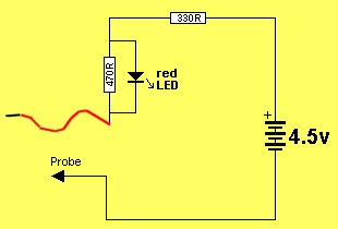
This. project is very simple. It is just a 4.5v supply with a LED and resistor in series. When the two probes touch they complete the circuit and the “test LED” (the red LED) will illuminate. When the probes are across a LED, only the LED being tested will illuminate. If the “test LED” illuminates, the LED being tested is shorted.
 When a LED being tested is illuminated, it will drop between 1.7v and 3.6v due to the characteristic voltage drop across it (according to the colour). This leaves only 0.9v to 2.8v for the voltage across both the 470R and 330R resistors, as they are in series. Since both resistors are about the same value, the voltage across each resistor will be about 1.4v and this is not sufficient to illuminate the red LED. A simple but clever way of turning off the red LED when a LED is being tested. It only turns ON when a short-circuit is present.
 Here is a close-up of the tinned copper wire holding the cells in place. The wires on the top of the cell is thick tinned copper wire and the other wires under the cells are thin tinned copper wire.
 The cells are finally held tight by drawing the two wires together and joining them with a tiny dob of solder.
The tester also has two more features.
It will test a shorted LED and continuity of tracks.
The LED on the tester will illuminate when the probes touch each other and this proves the batteries are connected. This feature can also be used as a continuity tester and will also illuminate LEDs very faintly through the driver-resistors on the circuit you are testing.
Digital Multimeters (DMM’s) will illuminate all types of LEDs (with positive coming out the positive lead) but analogue meters using a single cell will not illuminate any LEDs. In addition, they will not illuminate two LEDs in series and many projects have two LEDs in series, making a segment of a 7-segment display.
The flying-lead is positive and the tip of the probe is negative.
The tester is very handy for testing the colour of a surface-mount LED before it is fitted to a project and also high-power LEDs as they do not have any identification.
The PC board and components for this project is available from Talking Electronics.com
PARTS LIST
1 – 330R resistor
1 – 470R resistor
1 – 3mm red LED
1 – 20mm nail for probe
1 – paper clip for probe
1 – 30cm red hook-up wire
3 – button cells – AG12
10cm tinned copper wire
30cm fine tinned copper wire
20cm very fine solder
1 – LED Tester PCB


