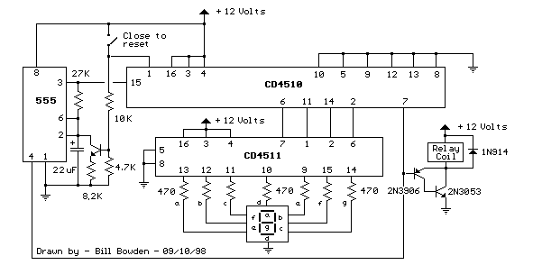
This circuit provides a visual 9 second delay using a 7 segment digital readout LED. When the switch is closed, the CD4010 up/down counter is preset to 9 and the 555 timer is disabled with the output held high. When the switch is opened, the timer produces an approximate 1 second clock signal, decrementing the counter until the 0 count is reached. When the zero count is reached, the ‘carry out’ signal at pin 7 of the counter moves low, energizing the 12 volt relay and stopping the clock with a low signal on the reset line (pin 4). The relay will remain energized until the switch is again closed, resetting the counter to 9. The 1 second clock signal from the 555 timer can be adjusted slightly longer or shorter by increasing or decreasing the resistor value at pin 3 of the timer.
 The CD4510 is a CMOS Presettable BCD Up/Down counter which can be preset to any number between 0 and 9 with a high level on the PRESET ENABLE line, (pin 1) or reset to 0 with a high level on the RESET line (pin 9). Inputs for presetting the counter (P1, P2, P3, P4) are on pins (4, 12, 13, 3) respectively. The counter advances up or down on each positive-going clock transition (pin 15) and the counting direction (up or down) is controlled by the logic level on the UP/DOWN input (pin 10, high=up, low=down). The CARRY-IN signal (pin 5) disables the counter with a high logic level.
The CD4511 is a CMOS BCD to 7 segment latch decoder capable of sourcing up to 25 mA which allows it to drive LEDs and other displays directly. A LATCH-ENABLE line (pin 5, active low) stores data from the BCD input lines. A LAMP-TEST input (pin 3, active low) can be used to illuminate all 7 segments, and a BLANKING input (pin 4, active low) can be used to turn all segments off. The LED display must be a common cathode type so that the segments are illuminated with a positive voltage on their respective connections. Complete data sheets for the CD4510 and CD4511.


