 Glue process in electronic manufacturing
Conductive and non-conductive joining processes are seeing rapid growth in electronic manufacturing thanks to improvements in the formulation of fluids, pumps and modern dispensing equipment. These technologies open up a wealth of applications such as MEMS packaging, exact LED positioning, heavy component placement or power modules to name just a few. Moreover, these technologies also remove some of the design constraints inherent with double sided reflow soldering. The application of SMT glues for double sided boards goes back many years and was considered a challenging and unreliable process. Typically, it involved either contact dispensing with a needle and stand-off, or screen printing the glue with a stencil. The former had heavy restrictions on design, dot size and speed, while the latter caused smearing and yield loss if the stencil was not kept absolutely clean. The industry has overcome these restrictions with modern jet dispensing technology and specially formulated fluids which offer fast, reliable and cost efficient processes
Fast and reliable gluing
State of the art assemblies are required to fulfil mechanical, electrical and optical properties. They carry a vast array of components in varying shapes, sizes and weights, such as MELFS, connectors, chokes or optical components. Substrates often have difficult surfaces, can be made of plastics or ceramics, and can be difficult to handle. In light of miniaturization and microwave properties, the use of cavities and PoP assemblies is becoming ever so popular. SMT manufacturing also deploys a vast array of soldering and curing technologies that should match up with the assembly process. All of the above factors have great influence on the joining properties such as dot shape, shear strength and snap curing speed. SMT glues ensure that components are held in place reliably- they cure in minutes, before the solder paste starts to melt. Applied in the correct position and appropriate volume the glue ensures that components do not move, rotate, tombstone, or fall of the substrate. Moreover, the added mechanical strength improves the reliability of circuit assemblies in harsh environments.
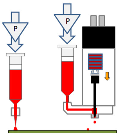
Traditional needle dispensing has numerous disadvantages with respect to speed, single dot size, process stability (tailing, repeatability, clogging) and lastly the need to contact the board. In contrast, jet dispensing overcomes these limitations by a large margin. The jet head can dispense from up to ¼ inch from the target surface and therefore be used on populated boards and cavities. Jet dispensing of glue dots has qualitative advantages over stencil printing and offers much higher flexibility as the number of dots and their size can be adjusted on the fly. Latest generation jet dispensers achieve 2.5 million dots per hour in line mode and more than 150’000 glue dots per hour in single dot mode. Depending on the size of a board and its design, jet dispensing can achieve higher throughputs than stencil printing.
Flexibility and stability of your glue process
As everyone knows, production managers have to be highly skilled to adapt their work orders to shifts in demand, equipment availability and manpower. A process that is highly productive, easily controlled and stable, but offers on-the-fly adjustments for prototypes and NPI boards is most welcome. In the following paragraphs we highlight some of the more important output parameters of today’s glue processes. One of the glue processes was implemented at the largest European electronic contract manufacturing company and more than a dozen manufacturing lines have been commissioned, giving prove to their robustness in 24/7 production.
Test
Equipment and experimental setup
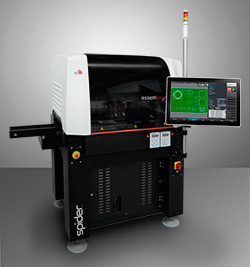
The experiments were carried out on a SPIDER High Speed Jet Dispenser manufactured by Essemtec AG. The machine was equipped with a piezo jet pump (VJV 3200). Two modern glues, optimized for high speed jet dispensing were chosen, for convenience named A and B. For both fluids the exact same pump setup such as nozzle diameter and tappet configuration was used. A calibrated glass plate was used to measure the xy coordinate of each dot. A specialized measurement equipment (CTQ) was used to measure the relative deviation from the etched coordinate grid on the glass plate using an optical, differential measurement mode. The same equipment is used to measure placement accuracy for pick & place machines. Speed tests were carried out using the IPC 9850A test board.
The following parameters were recorded:
- Speed and positioning accuracy (XY) according to IPC 9850A
- Volumetric process stability and drift as a function of time
- Screening of maximum and minimum dot size and dot geometry
Results
Speed and positioning accuracy (XY) according to IPC 9850A
Essemtec’s piezo jet pumps can be driven at up to 2000 Hz which translates into a theoretical shot rate of nearly 7.2 million dots per hour. In common SMT applications a maximum shot rate of 2.5 million shots per hour is applicable. Thus far, there is no published standard for dispensing speed, making comparisons between different platforms rather difficult. Hence we propose to adopt the test procedure as per the IPC 9850A while jetting 0.5mm dots. This IPC specification is being rolled out across the SMT industry for placement machines, and is very well known in the industry. To our knowledge, this is the first time that a comprehensive and comparable speed test is being published.
|
||||||||||||
Table 1 Positioning accuracy and speed as per IPC 9850A
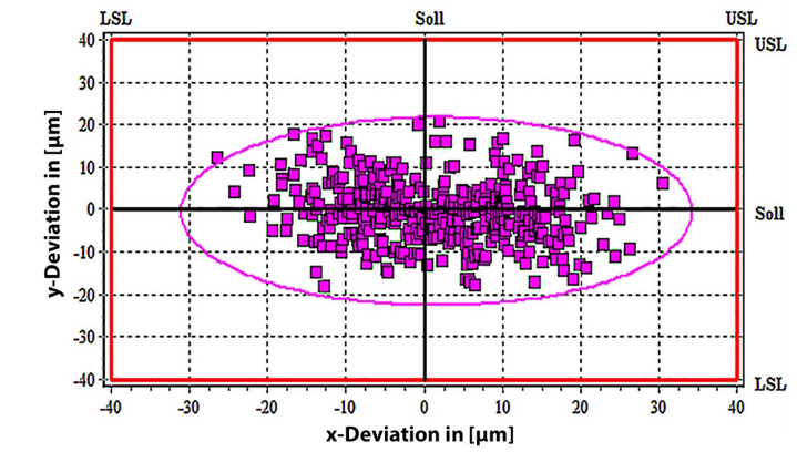
Both glues achieved very good speeds of over 50’000 dots per hour as shown in Table 1. The result means that a high speed jet dispenser like the Essemtec Spider will keep up with a placement machine rated as per IPC 9850A at 50’000 cph. The positioning accuracy of xy gantry systems is often not correctly reported in machine specifications. A common trick is to report accuracy at the machines lowest speeds, while bragging about machine speed and neglecting accuracy. Hence the IPC committee requires the accuracy AND the speed to be reported in the same test environment. It is of utmost importance to the end-user that the machine accuracy is reported at the maximum speed as shown in Figure 3. The XY deviation of 96, 0.5 mm dots is shown in this scatter plot for glue A. The measurements indicate a standard deviation of better than 30 µm @ 3 σ at a speed of over 50’000 dots per hour.
Volumetric process repeatability and drift as a function of time
Table 2 summarizes the results of the dot stability over a four hour experimental window. The diameters of the dots are remarkably stable and repeatable as seen from the standard deviation of the dot diameter. Even more notable is the ability of this equipment to achieve a huge range of dot sizes from 300 to 2000 mm with the same hardware setup. The dot size can be varied between these two extremes on the fly while the gantry moves from position to position. Each component thus receives the exact amount of glue irrespective of its size or when it was processed.
| Glue | Smallest
Dot Diameter |
Deviation
|
Largest
Dot Diameter |
Deviation
|
|
| Glue A | 300 µm ± 13@3 σ | 4.9 % | 1800 µm ± 48@3 σ | 3.0 % | |
| Glue B | 330 µm ± 20@3 σ | 5.7 % | 2000 µm ± 67@3 σ | 2.5 % | |
Table 2 Dot Diameter over the course of 4 hours
Figure 4 further depicts the process stability for glue A as a function of processing time. In this experiment, 416 dots of nominally 300 mm each were dispensed and measured. Then the machine was paused and the series repeated after 1 hour and again after 4 hours. As can be observed, there is no measurable process drift. The error margin of all measured points (3 x 416) is less than 5%. Each 300 mm dot weighs about 0.010 mg, as measured by a Mettler microbalance which is also part of the equipment. The results for both glues are similar. Thus we conclude that both glues can be jetted with excellent repeatability, stability and accuracy.

The experiment reveals that using the same piezo pump (VJV 3200) and a single hardware setup, dots of 300 to 1800 mm for glue A and 330 to 2000 mm for glue B can be achieved respectively. This range is sufficient to achieve excellent results for all conceivable applications in electronic manufacturing. With on the fly dot size adjustment and very good repeatability, the need for operator intervention is greatly reduced.
Process Window for Dot Geometry
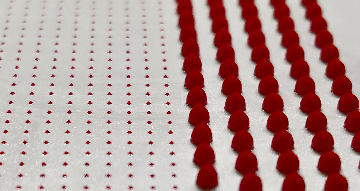
But how is it possible to achieve such a wide range of dot sizes using just one hardware setup? Essemtec’s piezo driver is voltage controlled in such a manner that the quality, geometry and energy of each dots can be precisely adjusted while the machine dispenses. Using ePlace software, the dot shape and size can be programmed for each board location if so desired. As can be seen in Figure 5, the aspect ratio (height to diameter) can also be adjusted by changing the dot energy. The energy of each dot can be programmed by changing the slew rate of the piezo voltage, while the open time determines the volume. This degree of freedom is equally important to be able to jet a wide range of materials with varying viscosities. Other factors to observe are the rheological properties of the fluid.
Summary
Glue dispensing processes are seeing a renaissance in today’s electronic manufacturing, driven by the need to place and keep components at a predetermined location, such as in LED lamps. Other drivers are the need for miniaturization, increased mechanical reliability and ease of manufacturing of combined SMT/THT boards. Double sided, reflow soldered boards rely on pad geometry and surface tension to keep the components on the bottom side. Designers can shrink pad geometries, place heavy components on both sides of the board and gain valuable foot print when relying on SMT glue dispensing. Expensive selective soldering processes can equally be eliminated. We have shown that the glue dispensing process is fast, reliable and has a big process window for dot shapes and size.


